Model 8640B TM 9-4935-601-14-7&P
SERVICE SHEET 22
PRINCIPLES OF OPERATION
General
The power supply assemblies provide five regulated dc supply voltages. The characteristics and
locations of each regulator are as follows:
Supply Voltage Limiting Assembly Service
Voltage Regulation Current Number Sheet No.
+44.6V ±10 mV 1A A20 22
+20V ±10 mV 0.7A A22 22
+5.2V ±10 mV 2.25A A20 22
-5.2V ±10 mV* 1.75A A18 23
-20V ±10 mV 0.7A A22 22
*With a temperature coefficient of -4.2 mV/° C.
Input Voltage (A12 and A14)
Main ac power enters the A14 Line Power Module, which contains the primary line fuse, an RFI filter,
and a printed circuit card switch which matches the transformer primary windings to the appropriate
line voltage. Power transformer T1 has a separate secondary winding for each regulator.
The A12 Rectifier Assembly contains five full-wave rectifiers and a crowbar to protect the instrument
from excessively high line voltages. The crowbar is across the output of the rectifier bridge to the
+44.6V regulator. If the rectified voltage exceeds 75V, breakdown diode VR1 conducts and triggers
the gate of SCR A12Q1. Q1 then conducts and blows the primary fuse.
+5.2V Regulator (A20)
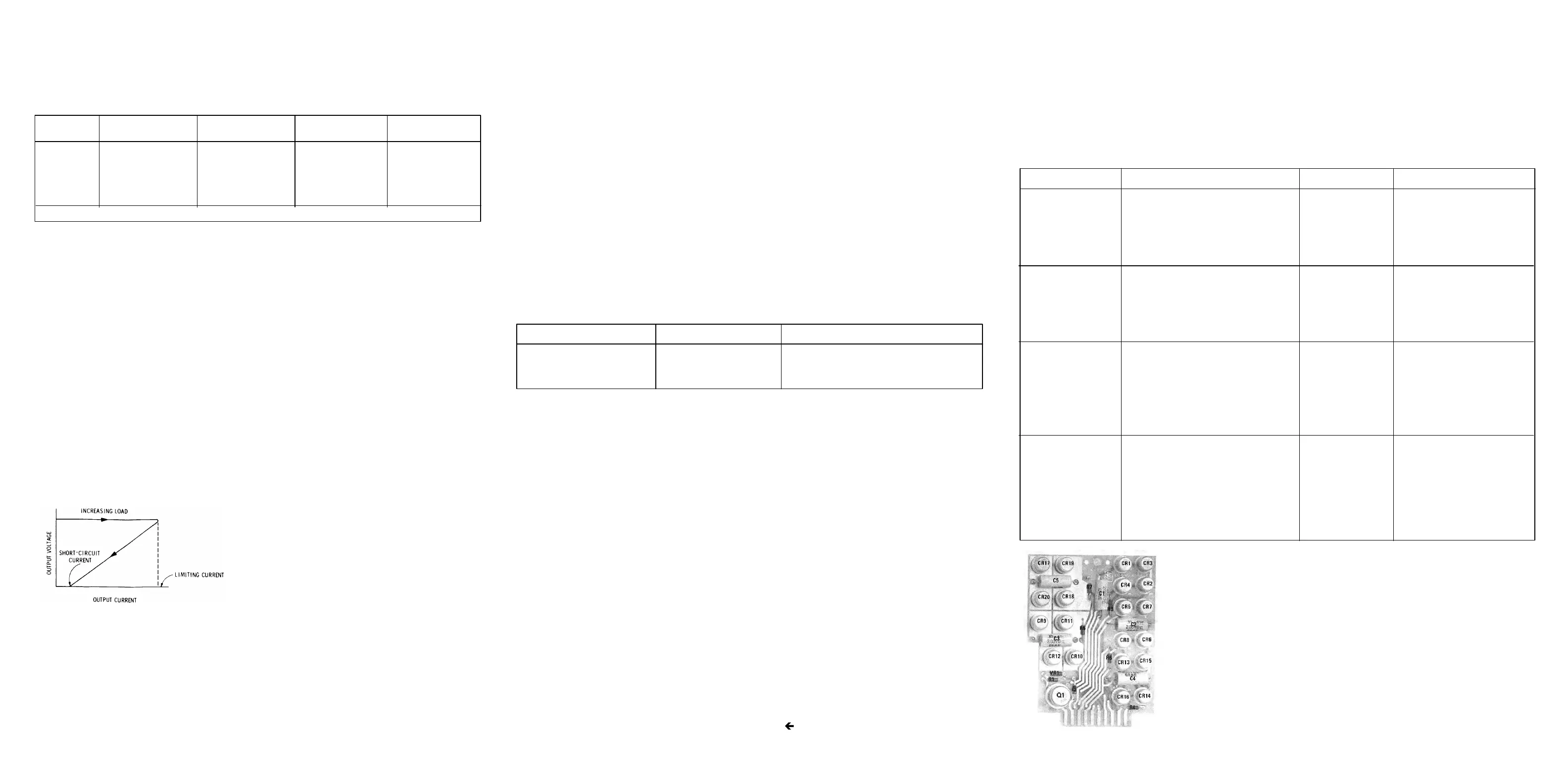
The +5.2V Regulator is a linear series type with current foldback for over-current protection and a
crowbar for over-voltage protection. The Voltage Regulator amplifier U1 compares the output
voltage with the (internal) divided-down reference voltage and drives transistor Q2 which in turn
drives the Series Regulator Transistor Q1 (chassis mounted) to regulate the current through it.
Current foldback is activated when the voltage across (and hence the current through) R25 and R26
exceeds the voltage across R19. The base-to-emitter junction between pins 1 and 10 of U1 (see
note on schematic) is then forward biased which reduces the drive to the Series Regulator transistor.
As shown in Figure 8-65, short-circuit current is quite low.
The output crowbar consisting of Q1, VR6, R23, and R24 protects against over-voltage outputs (due
for example to a shorted series pass transistor). An output voltage greater than about 6.2V triggers
Q1 which conducts and causes current foldback or blows Fl. Light-emitting diode DS2 is on only if
the output voltage is high enough to allow CR5 to conduct but not high enough to activate the
crowbar. Diode CR3 protects the regulator against reverse polarity load voltages. Diode CR4
protects Q1 against reverse bias.
+20V Regulator (A22)
The +20V regulator functions similarly to the +5.2V
regulator, except that the output voltage is reduced by
the voltage divider formed by R5, R6, and R7 and
compared directly with the zener diode reference at pin
4 of U2. Also, the series pass transistor base-emitter
junction is not in the current foldback circuit, resulting in
a larger short-circuit output current.
-20V Regulator (A22)
The -20V regulator functions identically to the +20V regulator, except that the -20V output is taken
from the point corresponding to the ground point on the +20V regulator, and the -20V ground return
is connected to a point that corresponds to the +20V output. Also, the -20V regulator uses VR3 for a
reference instead of the internal reference.
+44.6V Regulator (A20)
The +44.6V regulator functions similarly to the +5.2V regulator, except that the output voltage is
reduced by the voltage divider formed by R7, R8, and R9 and is applied to the non-inverting input of
the comparison amplifier of U2 (pin 3). The reference voltage is applied to the inverting input (pin 2).
The Series Regulator transistor Q3 (chassis mounted) is in the regulator return line and is driven by
Q4. The two transistors are in an inverted-Darlington configuration which is common emitter instead
of emitter follower as in the +5.2V regulator. Components Q3, Q6, R1, and R2 form a constant
current source which sinks the current from pin 6 of U2 and the base of Q4. Q5 provides foldback current
limiting.
TROUBLESHOOTING
It is assumed that one of the light-emitting diodes is not lit or that ripple, noise, or voltage from one of the
power supplies is suspect. Troubleshoot by using the test equipment listed below, performing the initial
test conditions, and following the procedures outlined in the text and the table.
Test Equipment
Digital Voltmeter............................................................................................................. HP 3480B/3484A
Oscilloscope..........................................................................................................HP 180A/1801A/1820C
Initial Test Conditions
Top cover removed (see Service Sheet F for removal procedure). Use extender board to extend desired
assembly (set instrument LINE power switch to OFF while removing or inserting circuit boards).
Initial Control Settings
LINE.....................................................................................................................................................ON
Rectifiers and Input Crowbar (A12)
If the Input Crowbar fires, causing the line fuse to blow, check the following:
1. Voltage Selection Card, P1, in A14 Line Power Assembly correctly set for line voltage.
2. All rectifier diodes and filter capacitors.
3. VR1, Q1, and associated components (Input Crowbar).
If one or two rectifier diodes in one of the bridge rectifiers are defective, ripple and noise could increase
without affecting the supply's average voltage or output current. Use the oscilloscope to measure ripple
and noise; connect the probe from the test points given below to chassis ground.
Supply Test Point Typical
Ripple and Noise
+44.6V A20TP1 <0.7 Vp-p
+20V A22TP1 <0.5 Vp-p
+5.2V A20TP6 <1 Vp-p
-20V A22TP6 <0.3 Vp-p
-5.2V A18TP1 <0.8 Vp-p
If one of the supplies is out of specification, check the rectifier diodes, filter capacitors, and associated
components. Also check the Series Regulator transistor.
If noise on a supply appears to be excessive check the reference (either internal or external) and its
associated filter capacitor and the regulator amplifier. Noise may either be of the broadband type (i.e.,
white noise) or it may consist of random jumps in level on the order of 1 mV (i.e., popcorn noise).
Regulator Circuits (A20 and A22)
The first step in solving a power supply problem is to ensure that the problem is caused by the power
supply. Minimum load resistances are given in the table for each supply. However, depending upon the
ohmmeter and resistance range used, measured resistance can vary from a few ohms to several kilohms.
So unless the load is actually shorted to ground, measuring load resistance doesn't always isolate the
problem.
Another way to isolate a power supply problem is to disconnect the supply from the load and check the
supply voltage. The quickest way to do this is to unsolder and lift pins on the extender board. However,
under some failure conditions, the regulator integrated circuit can regulate correctly with the load removed
from the power supply and yet cannot regulate correctly when the supply has its correct load.
To isolate a power supply problem to a specific circuit, use the data given in the table.
NOTE
The voltmeter input must float (i.e., both connections must be ungrounded) when
checking voltages with extender board pins open.
WARNING
Any adjustment, maintenance, and repair of the opened instrument under voltage
should be avoided as much as possible and, if inevitable, should be carried out
only by a skilled person who is aware of the hazard involved.
Capacitors inside the instrument may still be charged even if the instrument has
been disconnected from its source of supply.
Counter Phase Lock Circuits (A8A2)
SERVICE SHEET
Make sure that only fuses with the required rated current and of the specified type (normal
blow time delay, etc.) are used for replacement. The use of repaired fuses and the short-
circuiting of fuseholders must be avoided.
Whenever it is likely that the protection has been impaired, the instrument must be made
inoperative and be secured against any unintended operation.
Any interruption of the protective (grounding) conductor inside or outside the instrument or
disconnection of the protective earth terminal is likely to make the instrument dangerous.
Intentional interruption is prohibited.
Power Supply Troubleshooting (1 of 2)
Component or Circuit Test Conditions and Control Settings Normal Indication If Indication is Abnormal
-20V REGULATOR Remove A22 assembly. Measure resistance >30 Ω Check supply load circuits for short
from A17XA22-1 to chassis ground.
Open pins 5 and 26 on extender board. -20 ± 0.1V Check A22U1 and supply load
Extend A22 assembly and check voltage circuits
from A22 board pin 5 to A20TP9.
Check diodes and transistors for correct Correct operation and Replace faulty component
operation with voltage applied. Check resistance
components for correct resistance.
+20V REGULATOR Remove A22 assembly. Measure resistance >26Ω Check supply load circuits for short
from A17XA22-7 to chassis ground.
Open pins 7 and 24 on extender board. +20 ± 0.1V Check A22U2 and supply load
Extend A22 assy and check voltage circuits.
from A22TP5 to TP4.
Check diodes and transistors for correct Correct operation and Replace faulty component
operation with voltage applied. Check resistance
components for correct resistance.
+5.2V REGULATOR Remove A20 assy. Measure resistance >3Ω Check supply load circuits for short
from A17XA20-4, 7 to chassis ground.
Open pins 4, 27, 7, and 24 on +5.2 ± 0.15V Check A20U1 and supply
extender board. Extend A20 load circuits
assy and check voltage from
A20 board pin 1 to A20TP10.
Check diodes and transistors Correct operation and Replace faulty component
for correct operation with resistance
voltage applied. Check com-
ponents for correct resistance.
+44.6V REGULATOR Remove A20 assy. Measure re- >45Ω Check supply load circuits
sistance from A17XA20-15 for short
to chassis ground.
Open pins 13 and 18 on ex- +44.6 ± 0.1V Check A20U2 and supply
tender board. Extend A20 load circuits
assy and check voltage from
A20 board pin 13 to A20TP4.
Check diodes and transistors Correct operation and Replace faulty component
for correct operation with resistance
voltage applied. Check com-
ponents for correct resistance.
Figure 8-66. A12 Rectifier Assembly Component Locations
8-62
Figure 8-65. Current Foldback
Artisan Technology Group - Quality Instrumentation ... Guaranteed | (888) 88-SOURCE | www.artisantg.com