Model 8640B TM 9-4935-601-14-7&P Model 8640B TM 9-4935-601-14-7&P
SERVICE SHEET 10
PRINCIPLES OF OPERATION
Divider/Filter Assembly - General
The A10 Divider/Filter Assembly frequency-divides and filters
the signal from the RF oscillator. The divider network (see
Service Sheet 11) consists of a chain of nine binary dividers
(+2). The output is taken either from the RF oscillator buffer or
from an OR gate at the output of one of the dividers, depending
on the frequency range selected; all other divider output gates
are disabled and also the divider immediately following the
output divider. The output gates are transformer coupled out
and drive a power amplifier which drives the modulator (see
Service Sheet 12). The modulator controls the signal level and
adds AM.
The output from the dividers (and the modulator) is
approximately a square wave. The low-pass filters remove the
signal's harmonics. On the four lowest frequency bands, the
square wave output is quite symmetrical (i.e., second harmonics
are well suppressed). In the lower portion of these bands, the
filters suppress only the third harmonic and higher.
On higher frequency bands the divider output is more
asymmetrical and more second harmonic is present. Each of
these bands has two filters. In the lower portion of these bands,
the first filter's stop-band frequency is made low enough to
suppress the second harmonic. In the higher portion of the
band, a filter with a higher stop-band frequency is switched in to
suppress the second harmonic. The high-band filter is switched
in at approximately the geometric mean of the frequency
extremes of the band. A Schmitt Trigger (see Service Sheet 11)
senses a dc voltage, VT which is proportional to the frequency,
and relays switch the filters at the geometric mean. On the four
lowest bands, the low band filter for the 16 32 MHz range is also
switched in series with the band filters to improve the rejection
of high-order harmonics. All range switching is done by cam-
operated slide switches on the filter board (A10A1). The filters
drive the output amplifier which drives the RF output and AGC
circuits. The filters are inside the AGC feedback loop (see
Service Sheet 3).
RF Filters (A10A1)
The A10A1 RF Filter Assembly contains sixteen RF lowpass
filters and six slide switches that are controlled by the RANGE
switch. The filters for the four lowest bands (0.5 8 MHz bands)
are sharp-cutoff, elliptic-function filters. The remaining filters
are Chebishev filters. In the six highest bands, relays K1 and
K3 switch in the low band filters when the frequency is below the
geometric mean frequency of the range and relays K2 and K4
switch in the high band filters when above the geometric mean.
The slide switches route the RF signal to the proper filters,
activate the frequency dividers, and route the RF signal to and
from dividers. Each slider has three detented positions.
SERVICE SHEET 10 (Cont'd)
TROUBLESHOOTING
It is assumed that a problem has been isolated to the
RF Filter circuits as a result of using the
troubleshooting block diagrams. Troubleshoot by using
the test equipment listed below, performing the initial
test conditions and control settings, and following the
procedures outlined in the table.
Test Equipment
Digital Voltmeter................................ HP 3480B/3484A
Initial Test Conditions
Top cover removed (see Service Sheet F for removal
procedure).
A10 Divider/Filter Assembly casting cover removed,
A10A2 RF Divider Assembly removed and extended
for service with access to A10A1 RF Filter Assembly
(see Service Sheet D for procedures).
Initial Control Settings
Meter Function ..................................................VOLTS
COUNTER MODE: EXPAND .................................. Off
LOCK ............................................ Off
Source............................................INT
AM ........................................................................OFF
FM ........................................................................ OFF
RANGE ................................................ 256 - 512 MHz
FREQUENCY TUNE ..................................... 550 MHz
OUTPUT LEVEL ............................................--10 dBm
RF ON/OFF.............................................................ON
RF Filter Circuits
The quickest way to isolate a divider/filter problem is to
use the front panel controls to set various frequencies
and frequency ranges while monitoring the output
voltage meter. Usually a problem will appear as shown
in the following table.
SERVICE SHEET 10 (Cont'd)
Symptom Probable Cause
No output on one band Defective output circuit for
only one of the dividers, a filter,
or a slide switch
No output on one band Defective divider or 16 - 32
and all bands below that MHz low band filter or 0.5
band to 8 MHz divider output
transformer
Low power at highest end Defective geometric mean
of bands (8 to 1024 MHz) switching (high band filters
only not being switched in)
Overly high harmonics at Defective geometric mean
lowest end of bands (8 to switching (low band filters
1024 MHz) only not being switched in)
Intermittent power Poor contact on slide switch
Changing bands does not Loose coupler between
change output frequency RANGE switch and Divider/
even though the counter Filter switch assembly
may indicate a change
The dividers and the Schmitt Trigger circuits are shown and
discussed on Service Sheet 11 (the relays driven by the Schmitt
Trigger circuits are shown on this service sheet).
NOTE
The following procedure checks gross
failure. A more comprehensive check can
be made by performing the Filter
Adjustment in Section V.
Variable-Frequency Modulation
Oscillator for Option 001 (All, A13)
SERVICE SHEET 9A
SERVICE SHEET 10 (Cont'd)
RF Filter Troubleshooting
Component Test Conditions and Normal Indication If Indication
or Circuit Control Settings is Abnormal
HIGH/LOW BAND Initial conditions and DC continuity across con- Check K2, K4, and
RELAYS (A10A1) settings tacts of K2 and K4 associated circuitry
Set FREQUENCY DC continuity across con- Check K1, K3 and
TUNE to 256 MHz tacts of K1 and K3 associated circuitry
RF FILTERS Initial conditions and -10 dBm on panel meter Check appropriate
(A10A1) settings then set switch contacts and
RANGE to each posi- appropriate high and
tion and tune FRE- low band filters
QUENCY TUNE full
cw and full ccw
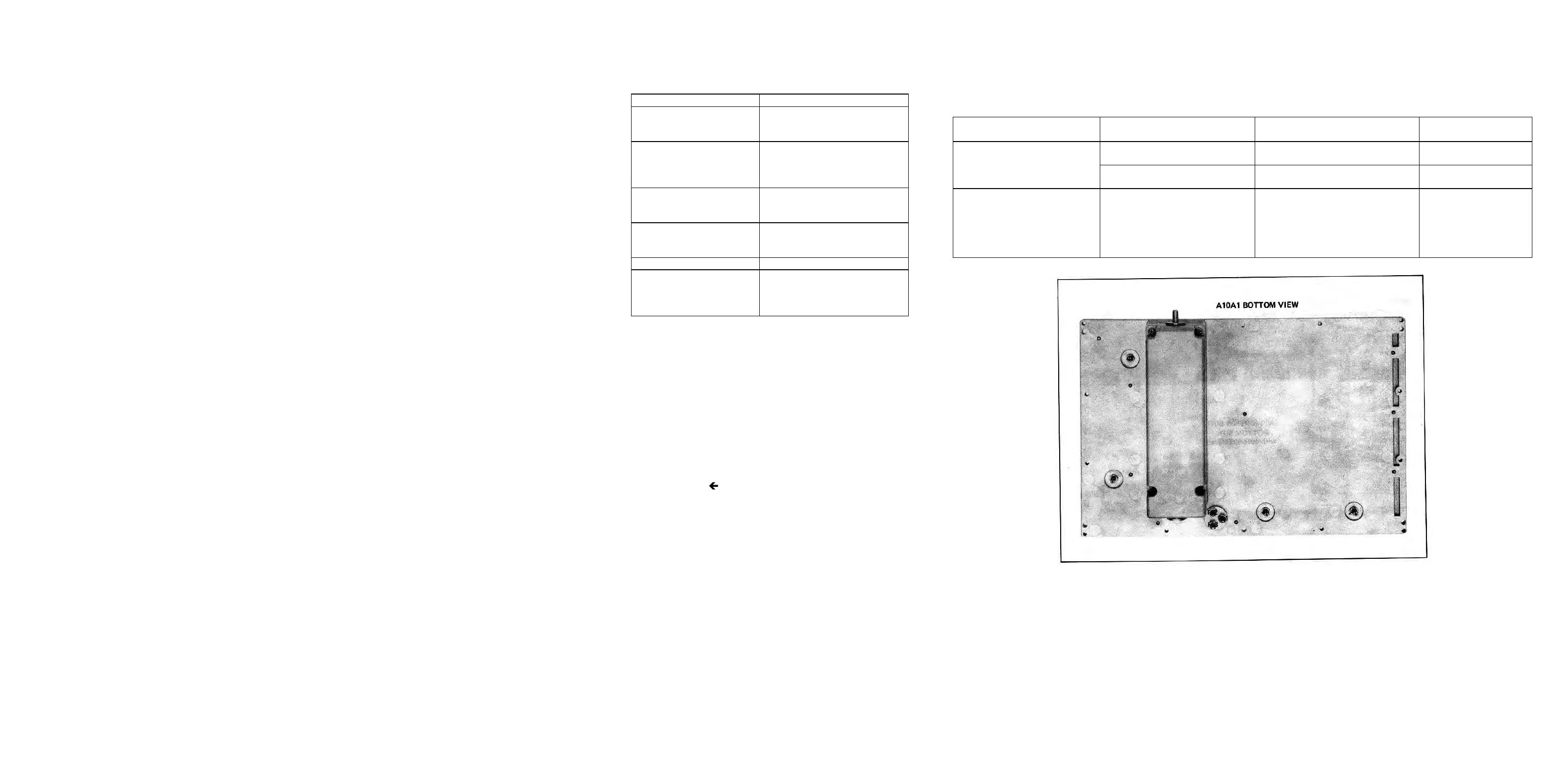
Figure 8-36. A10A1 RF Filter Assembly Component Locations (1 of 2).
8-38
Artisan Technology Group - Quality Instrumentation ... Guaranteed | (888) 88-SOURCE | www.artisantg.com