Model 8640B TM 9-4935-601-14-7&P
SERVICE SHEET 23
PRINCIPLES OF OPERATION
-5.2V Regulator (A18)
The -5.2V regulator functions similarly to the +5.2V regulator described on Service Sheet 22, except that the -5.2V output
is taken from the point corresponding to the ground point on the +5.2V regulator, and the -5.2V ground return is connected
to a point that corresponds to the +5.2V output. In addition, diodes CR2 and CR3 give the output voltage a small negative
temperature coefficient.
Fan Motor and Fan Driver (A18)
Fan Motor A16B1 is a brushless, dc motor comprising a cylindrical, permanent magnet rotor and a four-section stator
winding. The motor's stator windings are energized sequentially by the Fan Driver circuit. Two Hall generators are located
on the stator, 900 apart. In the presence of a magnetic field, each Hall generator will produce two out-of-phase voltages at
its two output terminals. The magnitude of the voltage is proportional to the strength of the field and the amount of bias
current. The phase is determined by the polarity of the field. The Hall generators sense the position of the rotor and turn
on the appropriate drive transistors.
Fan Speed Regulator (A18)
An emf which is proportional to rotor speed is generated in the unenergized stator windings. Diodes CR1, CR4, CR7, and
CR11 detect this emf and charge C4 to a negative voltage. Current source Q1 discharges C4 at a constant rate. The
voltage across C4 plus the constant voltage drop across R15 is the base voltage of Q4. If rotor speed decreases, the
voltage across C4 becomes less negative, the base of Q4 becomes more positive and Q4 more heavily biases the Hall
generators. The drive transistors turn on harder and rotor speed increases.
TROUBLESHOOTING
It is assumed that the light-emitting diode is unlit or that ripple, noise, or voltage from the -5.2V power supply is suspect, or
that the fan is operating erratically or not at all. Troubleshoot by using the test equipment listed below, performing the
initial test conditions, and following the procedures outlined in the text and the table.
Test Equipment
Digital Voltmeter ............................................................................................................................... . HP 3480B/3484A
Oscilloscope................................................................................................................................HP 180A/1801A/1820C
Initial Test Conditions
Top cover removed (see Service Sheet F for removal procedure). Use extender board to extend desired assembly (set
instrument LINE power switch to OFF while removing or inserting circuit boards).
Initial Control Settings
LINE...........................................................................................................................................................................ON
Regulator Circuits (A18)
The first step in solving a power supply problem is to ensure that the problem is caused by the power supply. Minimum
load resistances are given below for the supply. However, depending upon the ohmmeter and resistance range used,
measured resistance can vary from a few ohms to several kilohms. So unless the load is actually shorted to ground,
measuring load resistance doesn't isolate the problem.
Another way to isolate a power supply problem is to disconnect the supply from the load and check the supply voltage. The
quickest way to do this is to unsolder and lift pins on the extender board. However under some failure conditions, the
regulator integrated circuit can regulate correctly with the load removed from the power supply and yet cannot regulate
correctly when the supply has its correct load.
To isolate a power supply problem to a specific circuit, use the data given in the table.
NOTE
The voltmeter input must float (i.e., both connectors must be ungrounded) when checking voltages
with extender board pins open.
Fan Driver and Speed Regulator (A18)
If one or two of the fan's windings are open or are not being supplied with the correct voltage, the fan may not start in all
positions. However, once started, it may run correctly. Use the data given in the table to isolate a problem to a specific
circuit. Also check that the fan blade does not hit against the rear vent. If it does, loosen the setscrew and slide the blade
forward.
Power Supply Circuits (A12, A14, A20, A22)
SERVICE SHEET 22
SERVICE SHEET 23 (Cont'd)
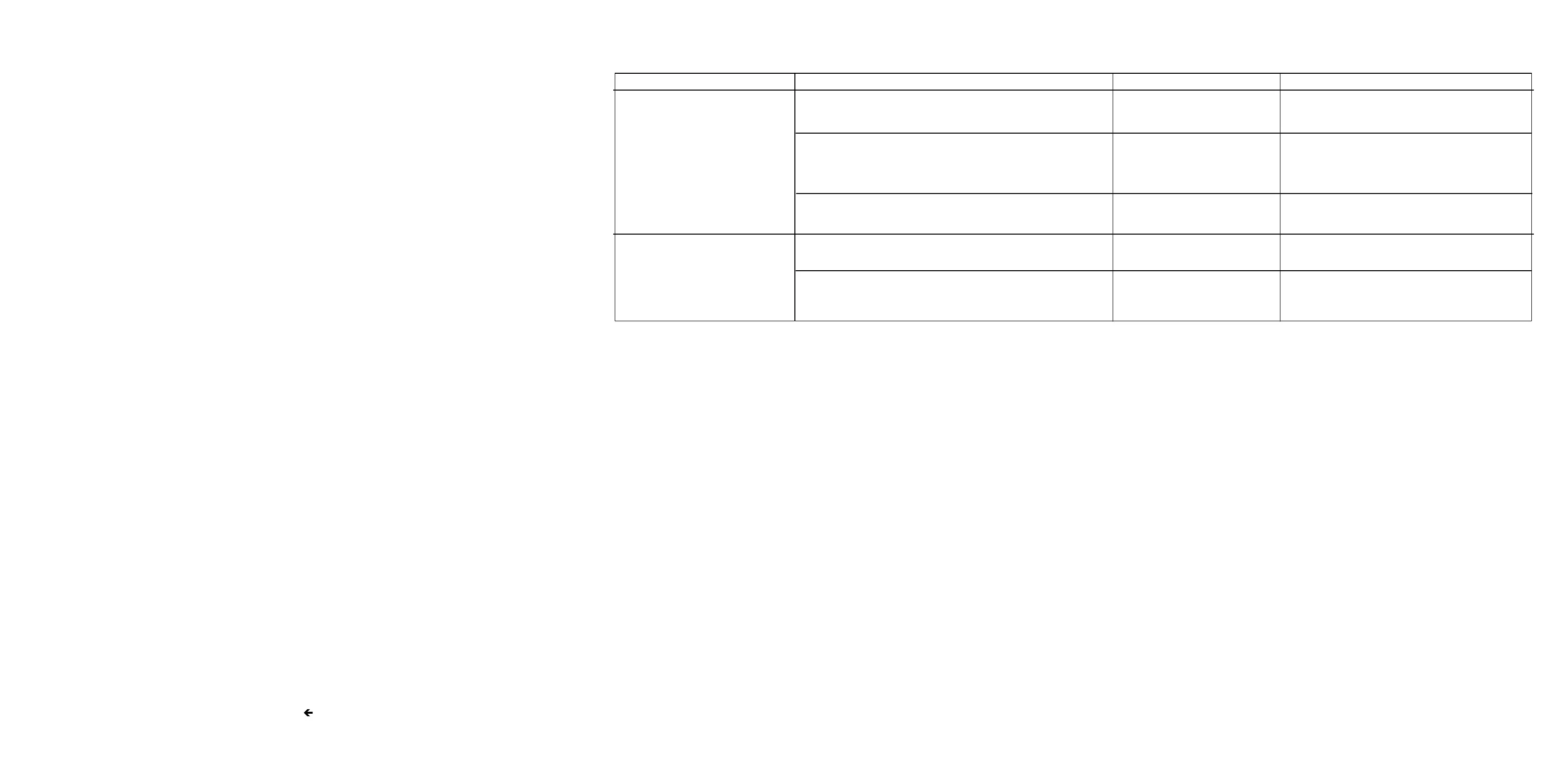
Regulator and Fan Driver Troubleshooting
Component or Circuit Test Conditions and Control Settings Normal Indication If Indication is Abnormal
-5.2V REGULATOR Remove A18 assy. Measure >392 Check supply load circuits
resistance from A17XA18-6, for short
14 to chassis ground.
Open pins 15 and 16 on ex- -5.2 ± 0.1V Check A18U1 and supply
tender board. Extend A18 load circuits
assy and check voltage
from A18 board pin 15 to
A18TP5.
Check diodes and transistors Correct operation and Replace faulty component
for correct operation with resistance
voltage applied. Check components for correct resistance.
FAN DRIVER Measure voltage applied to As shown on Check appropriate components.
each winding of motor schematic
(approximately sinusoidal)
Measure period of voltages As shown on Check speed regulator
applied to windings of schematic circuits
motor
8-64
Artisan Technology Group - Quality Instrumentation ... Guaranteed | (888) 88-SOURCE | www.artisantg.com