Model 8640B TM 9-4935-601-14-7&P
PERFORMANCE TESTS
4-18. SUB-HARMONICS AND NON-HARMONIC SPURIOUS TEST (Cont'd)
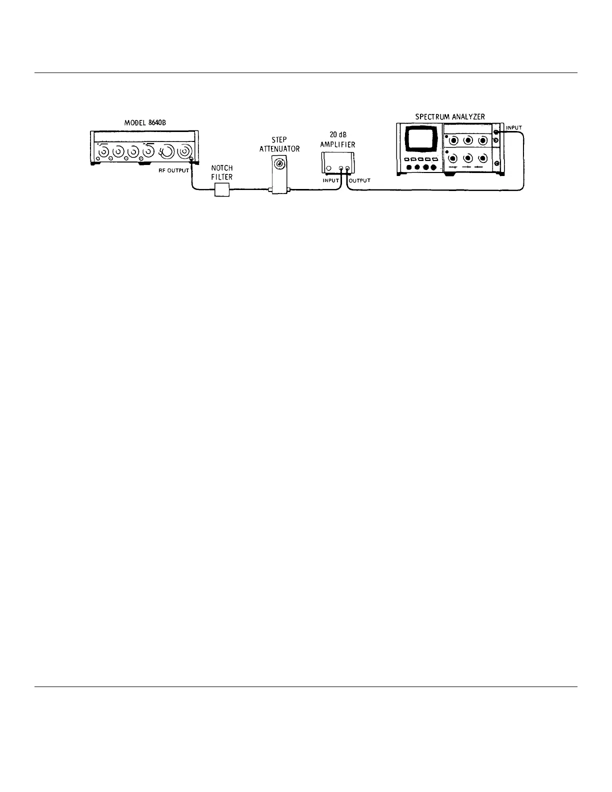
Figure 4-5. Sub-Harmonics and Non-Harmonic Spurious Test Setup
EQUIPMENT:
520 MHz Notch Filter..................................................................................... HP 08640-60502
10 dB Step Attenuator................................................................................................ HP 355D
20 dB Amplifier.........................................................................................................HP 8447A
Spectrum Analyzer ...............................................................................HP 141T/8552B/8554B
PROCEDURE:
1. Connect equipment as shown in Figure 4-5 after setting Signal Generator's controls as follows:
Meter Function .....................................................................................................................................LEVEL
COUNTER MODE: EXPAND...................................................................................Off
LOCK........................................................................................Off
Source ..................................................................................... INT
AM............................................................................................................................................................OFF
FM............................................................................................................................................................OFF
RANGE ...................................................................................................................................... 128-256 MHz
FREQUENCY TUNE .........................................................................................................................260 MHz
OUTPUT LEVEL................................................................................................................................+13 dBm
RF ON/OFF................................................................................................................................................ON
2. Set step attenuator to 60 dB. Set analyzer's input attenuation to 0 dB, scale switch to log (10 dB/div), and
reference level controls to -30 dBm; set resolution bandwidth to 30 kHz, frequency span per division (scan width) to
1 MHz, and tune the frequency controls to set 260 MHz at the center of the display. Adjust reference level vernier
to set signal peak to top (reference) graticule line on display.
3. Set generator's RANGE switch to 256 - 512 MHz. Tune analyzer to display the 520 MHz signal (i.e., the second
harmonic of 260 MHz).
4. Tune generator's FREQUENCY TUNE for a minimum signal on analyzer's display. Set the step attenuator to 0 dB,
and again tune FREQUENCY TUNE for a minimum signal.
5. The signal on the display should be below the top (reference level) graticule line. Tune the spectrum analyzer
slowly to 500 kHz. All non-harmonic spurious signals, and sub-harmonics should be below the -40 dB graticule on
the display (> 100 dB down).
100 dB __________________________
4-14
Artisan Technology Group - Quality Instrumentation ... Guaranteed | (888) 88-SOURCE | www.artisantg.com