Model 8640B TM 9-4935-601-14-7&P
ADJUSTMENTS
5-39. FM LINEARITY ADJUSTMENT (Cont'd)
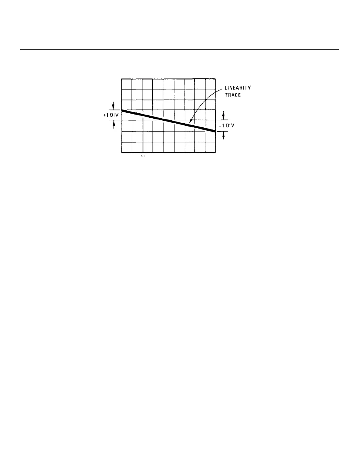
Figure 5-8. FM Linearity Display
5. Set linearity circuit's output switch to ref φ + var φ and the voltage divider switch to 1. This calibrates the display
for 1% error in linearity per division.
6. Adjust variable-phase generator's variable phase output's phase and linearity circuit's var ∅ level control for the
best possible horizontal straight line over center portion of trace.
7. Adjust POS SHAPING and NEG SHAPING adjustments, A7R12 and A7R41, for the best possible horizontal
straight line at both ends of the trace (but within + one major division or + 1%).
8. Perform the FM Sensitivity Adjustment, paragraph 5-40.
5-40. FM SENSITIVITY ADJUSTMENT
REFERENCE:
Service Sheets 6 and 7.
DESCRIPTION:
The Signal Generator is frequency modulated with an accurate, 1 Vpk, 16.63 kHz signal. The modulated RF output is
monitored on a spectrum analyzer and FM sensitivity is adjusted for the first carrier (Bessel) null. The adjustments are
made at mid-band and at both band ends. (Peak deviation = 2.405 xf
mod
at first carrier null.)
NOTE
The FM Linearity Adjustment (5-39) should be made before performing this adjustment.
5-32
Artisan Technology Group - Quality Instrumentation ... Guaranteed | (888) 88-SOURCE | www.artisantg.com