Model 8640B TM 9-4935-601-14-7&P
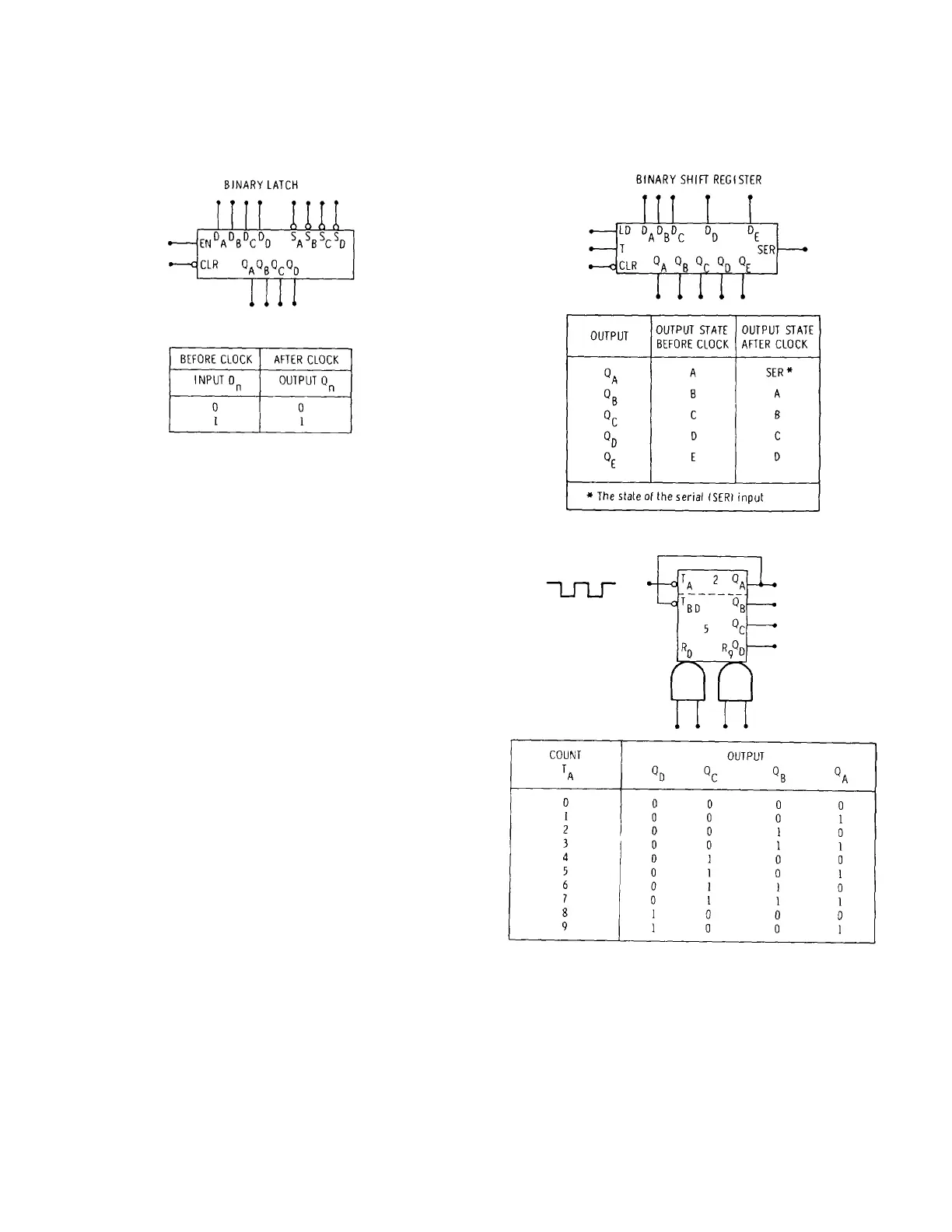
8-60. A low at the clear (CLR) input clears all outputs to
a low independent of the clock. The clear input
overrides the load input.
Figure 8-9. Binary Latch
8-61. Decade Counters and Symbols 8-62. Basic
Counter. The basic decade counter (or scaler or
divider), shown in Figure 8-11, has ten logic states. The
active-high outputs (Q
A
, Q
B
, Q
C
, and Q
D
) increment by
one BCD count each time the trigger (T
A
) or clock input
goes from a high to a low. The count sequence is also
shown in the figure. The counter may be subdivided
into a divide-by-two and a divide-by-five counter. The
two counters are connected in series (the Q
A
output
connected to the T
BD
input) to obtain a divide-by-ten
counter. The counter has two ANDed clear or reset-to-
zero (R
0
) inputs. When both R
0
inputs are high, the
outputs clear to zero. The clear function overrides the
clock. Similarly, the two ANDed set or reset-to-nine (R
9
)
inputs set the outputs to the nine count. If all reset-to-
zero and reset-to-nine inputs are simultaneously high,
the reset-to-nine overrides the reset-to-zero.
8-63. Programmable Counter. The programmable
decade counter, shown in Figure 8-12, operates
similarly to the basic decade counter when the load (LD)
input is high. The counter shown has only a single clear
(CLR) input which is active-low. When the load input is
low, the information at the data (or preset) inputs (D
A
,
D
B
, D
C
, and D
D
) is transferred to the outputs at the next
high going clock (T) input. The outputs remain in the
preset state until the load input returns to a high and the
trigger (T) or clock input again goes high at which time
the count increments by one. The counter may be
preset to a count greater than nine, but in such cases
the count proceeds as shown in the state diagram.
Figure 8-10. Binary Shift Register
Figure 8-11. Basic Decade Counter (Scaler)
8-9
Artisan Technology Group - Quality Instrumentation ... Guaranteed | (888) 88-SOURCE | www.artisantg.com