Model 8640B TM 9-4935-601-14-7&P
ADJUSTMENTS
5-40. FM SENSITIVITY ADJUSTMENT (Cont'd)
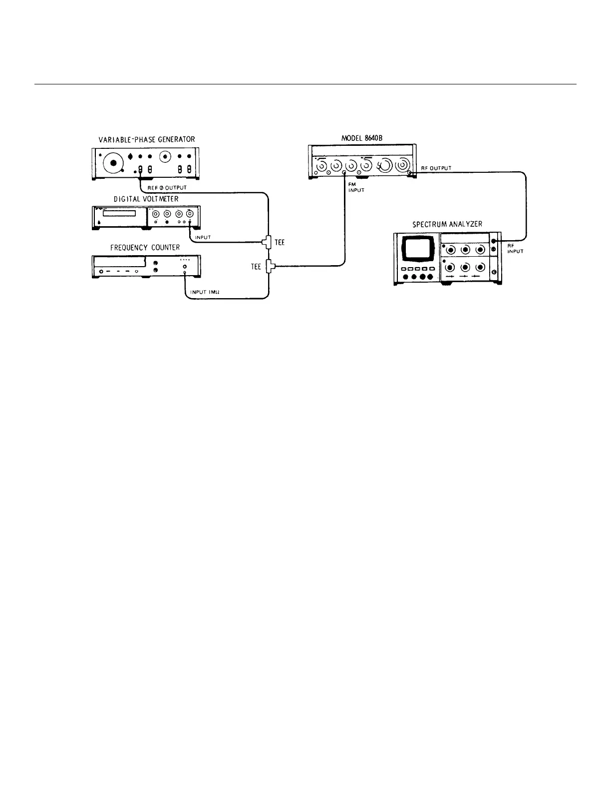
Figure 5-9. FM Sensitivity Adjustment Test Setup
EQUIPMENT:
Variable-Phase Generator.......................................................................................... HP 203A
Digital Voltmeter............................................................................................ HP 3480B/3484A
Frequency Counter ................................................................................................... HP 5327C
Spectrum Analyzer ................................................................................ HP 141T/8552B/8553B
PROCEDURE:
1. Connect equipment as shown in Figure 5-9 after setting Signal Generator's controls as follows:
Meter Function..................................................................................................................... FM
COUNTER MODE: EXPAND............................................................................................... Off
LOCK ................................................................................................... Off
Source ................................................................................................. INT
AM....................................................................................................................................... OFF
FM ...................................................................................................................................... OFF
PEAK DEVIATION........................................................................................................ 40 kHz
PEAK DEVIATION Vernier .......................................................................................... Full cw
RANGE................................................................................................................... 16 - 32 MHz
FREQUENCY TUNE.................................................................................................. 24 MHz
OUTPUT LEVEL........................................................................................................ -37 dBm
RF ON/OFF . ..................................................................................................................... ON
2. Set spectrum analyzer's center frequency to 24 MHz, resolution bandwidth to 3 kHz frequency span (scan width)
per division to 20 kHz, and input attenuation to 0 dB. Center signal on display and use reference level controls
(set for 10 dB/division) to set signal peak to top (0 dB reference) graticule line on display.
5-33
Artisan Technology Group - Quality Instrumentation ... Guaranteed | (888) 88-SOURCE | www.artisantg.com