Model 8640B TM 9-.4935-601-14-7&P
1-33. If an output frequency between adjacent counter
indications is required, a TIME BASE VERNIER is
provided with a range of +20 ppm. This fine tunes the
internal crystal time base and sets the output frequency
between adjacent counts (i.e., the digits to the right of
the display). This gives continuous coverage of all
output frequencies even in the phase lock mode. An
UNCAL light near the vernier will indicate when this
mode has been selected since the counter display is
incorrect.
1-34. When phase locked, FM capability is preserved
down to modulation rates of <50 Hz. The narrow
bandwidth of the phase lock loop (<5 Hz) allows FM up
to 250 kHz rates and assures no degradation in noise
from the unlocked mode. The generator's residual FM
is not changed by phase lock.
1-35. Amplitude Modulation 1-36. AM is variable from
0 to 100% with the bandwidth, accuracy, and low
incidental FM required for the most stringent AM
applications. The front panel meter gives a direct
readout of AM% in either the internal or external mode
and autoranges the 0 -100% scale at 0 30% for
improved settability at low modulation depth.
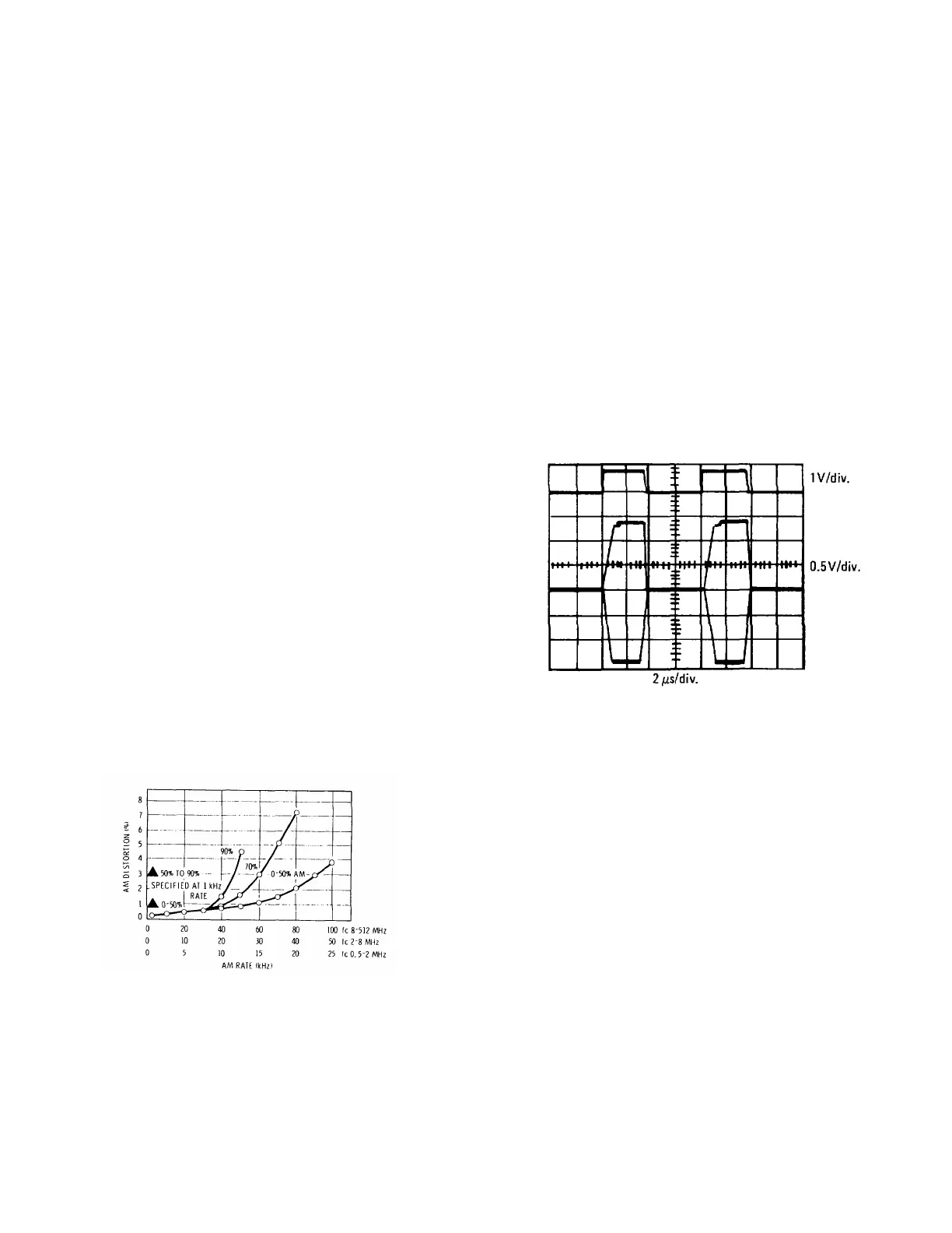
1-37. AM up to bandwidths of 60 kHz is possible
depending on carrier frequency and modulation depths.
Distortion is specified at 400 Hz and 1000 Hz to be <1%
up to 50% AM, <3% to 90% AM. Figure 1-4 shows
measured AM distortion characteristics for other
modulation frequencies.
Note that for 0- 50% AM, distortion is <1% to
approximately 50 kHz for an output frequency of 200
MHz.
Figure 1-4. AM distortion us AM rate measured at
200 MHz and +13 dBm, but applies to all bands.
(Supplemental information only.)
1-38. Pulse Modulation
1-39. Also included on the AM function switch is a
position for external PULSE modulation. In this mode,
pulse inputs with repetition rates to 500 kHz and widths
down to 2 us can be applied to modulate the RF carrier.
Rise and fall times vary with output frequency down to <
1 us from 8 to 512 MHz.
1-40. Pulse inputs turn the RF on. Hence with no pulse
input the RF will read approximately zero on the built-in
level meter. For pulse inputs within the specified range,
the RF output calibration is preserved and the level
meter reads the pulse-on power of the RF output. For
repetition rates below that specified, the pulsed RF
output is still available but the pulse-on level is no
longer calibrated or metered.
Figure 1-5. Pulsed RF 20 MHz Carrier Frequency
1-41. Frequency Modulation
1-42. FM is calibrated, metered and constant with
frequency and band changes. Peak deviations to at
least 0.5% of carrier frequency are available (i.e., 1% of
the minimum frequency in each octave band). On the
256 512 MHz band, for example, the maximum
deviation is 2.56 MHz peak or 5.12 MHz peak-to-peak.
With this wide deviation capability, it is possible to
sweep the generator, using the dc coupled FM mode
and a sawtooth input, to test and align IF filters and
discriminators.
1-4
Artisan Technology Group - Quality Instrumentation ... Guaranteed | (888) 88-SOURCE | www.artisantg.com