Model 8640B TM 9-4935-601-14-7&P
b. When K is high and J is low, Q will go low
(unless it is already low).
c. When K is low and J is high, Q will go
high (unless it is already high).
d. When K and J are both high, the flip-flop will
toggle. That is, if Q is high, the trigger pulse will set Q
low, and if Q is low, the trigger pulse will set Q high.
8-50. The set (S) and clear (CLR) inputs override all
other input conditions: when S is low, Q is forced high;
when CLR is low, Q is forced low. Although normally the
Q output is the compliment of the Q output,
simultaneous low inputs at S and CLR will force both Q
and Q high on some J/K flip-flops.
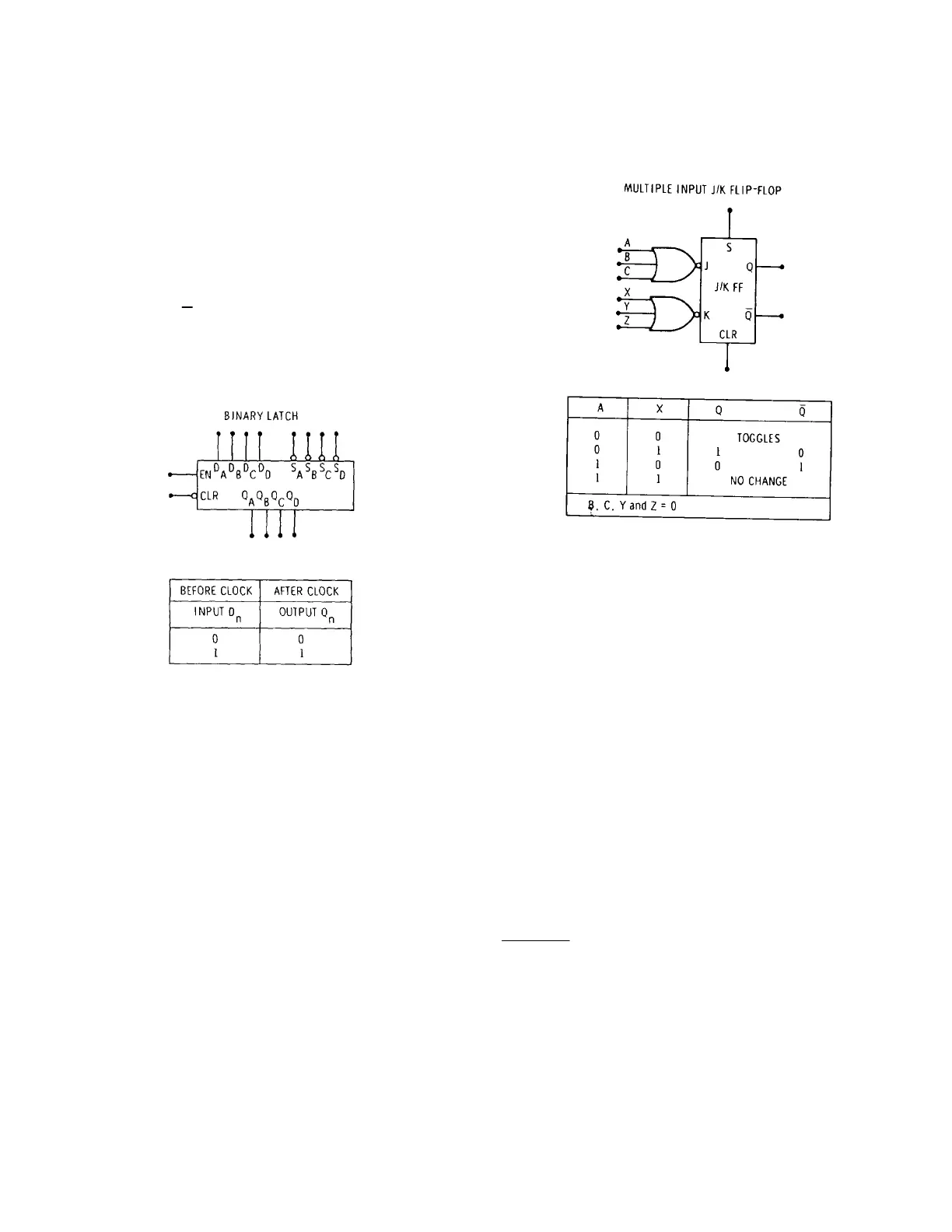
Figure 8-7. J/K Flip-Flop
8-51. Multiple Input J/K Flip-Flop. A multiple input J/K
flip-flop is shown in Figure 8-8. It behaves like a J/K
flip-flop with NORed inputs: if A, B and C are low, J is
high, if A, B or C is high, J is low. A J-related and a K-
related input may be tied together to form a trigger
input; in this case the trigger would be active-low (if all
other inputs are low).
8-52. Binary Registers
8-53. Binary Latch
8-54. The four bit binary register shown in Figure 8-9 is
used as a storage latch. Information at the data (D
n
)*
inputs is transferred to the respective Q
n
outputs when
the enable (EN) input is low. When the enable goes
high, the outputs are latched and are no longer affected
by the data inputs.
Figure 8-8. Multiple Input J/K Flip-Flop
8-55. When enabled, any output may be set (to a high)
by a low on the respective set (S
n
) input which overrides
the data input. When not enabled, the set inputs have
no effect on the outputs. 8-56. A low on the master
clear (CLR) input overrides all other conditions and
forces all outputs low.
8-57. Binary Shift Register
8-58. A five bit binary shift register is shown in Figure 8-
10. Information of the data (D
n
)* inputs is transferred to
the respective Q
n
outputs when the load (LD) input is
high. The load input is independent of the clock (T)
input.
8-59. If the load input is low, a high going clock pulse
shifts the output to the next adjacent output (e.g., the
output at Q
B
now appears as the output of Q
C
). Also,
the input state at the serial (SER) input appears at the
Q
A
output.
* n = A, B, C, or D
8-8
Artisan Technology Group - Quality Instrumentation ... Guaranteed | (888) 88-SOURCE | www.artisantg.com