Model 8640B TM 9-4935-601-14-7&P
ADJUSTMENTS
5-31. OUTPUT LEVEL VERNIER AND METER ADJUSTMENT (Cont'd)
This procedure uses an IF substitution technique in which the spectrum analyzer's IF is the standard. The IF step
accuracy should be within ±0.2 dB overall. The IF step accuracy can be checked using the above technique by
comparing a lab calibrated attenuator (such as HP Model 355D Option H36) with the IF step control at the frequency of
attenuator calibration (e.g., 3 MHz for the HP 355D Option H36).
NOTE
1. Check that the Output Level Knob Adjustment (5-30), the RF Detector Offset Adjustment (5-29), and
the Meter Adjustments (5-28) are correct before performing this adjustment.
2. After making meter adjustments which are accessible only from the bottom of the instrument, check
the adjustment with the instrument in its normal operating position.
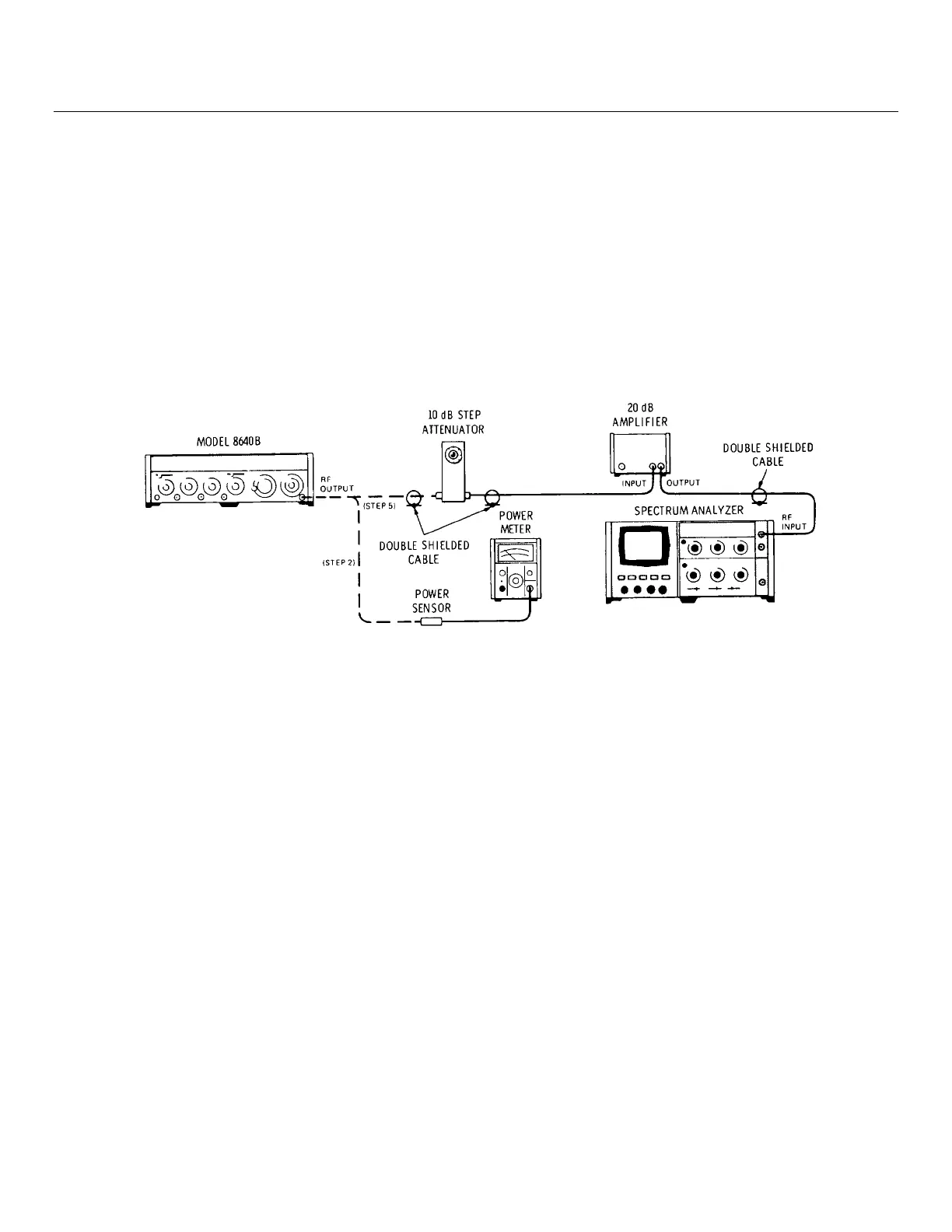
Figure 5-1. Output Level Vernier and Meter Adjustment Test Setup
EQUIPMENT:
Spectrum Analyzer...........................................................HP 141T/8552B/8553B
Power Meter...........................................................................................HP 435A
Power Sensor.......................................................................................HP 8481A
20 dB Amplifier .................................................................................. HP 8447A
Double Shielded Cable (3 required)..............................................HP 08708-6033
NOTE
An HP Model 432A Power Meter with a Model 478A Thermistor Mount can be used for this test.
However, a 10 dB attenuator, such as the Model 8491A OPT 10, must be used with the mount. This will
slightly degrade measurement accuracy.
5-15
Artisan Technology Group - Quality Instrumentation ... Guaranteed | (888) 88-SOURCE | www.artisantg.com