Model 8640B TM 9-4935-601-14-7&P
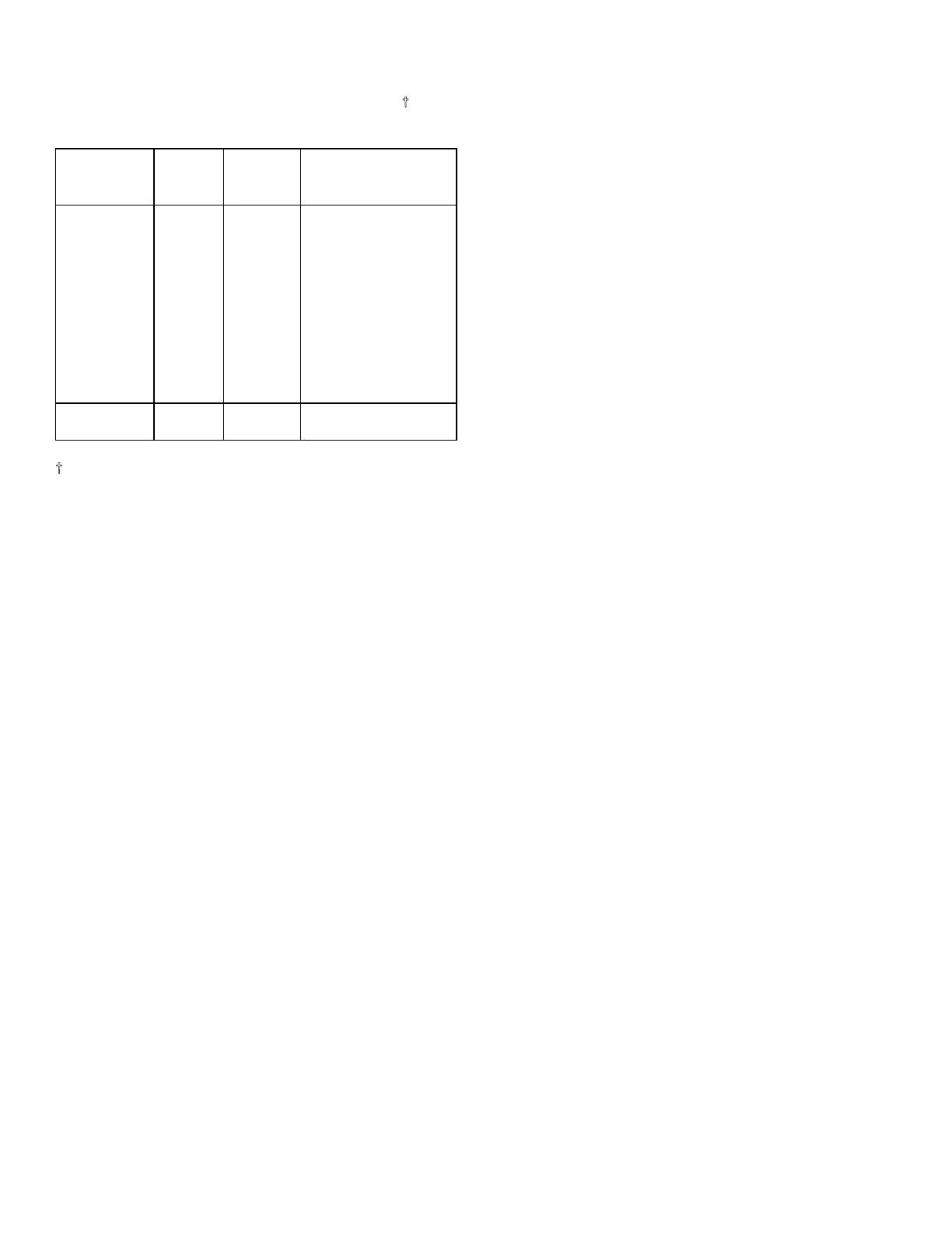
Table 5-1. Factory Selected Components
(2 of 2)
Service Range of
Component Sheet Values Basis of Selection
A11R28 9A 215 to See paragraph 5-27.
(Option 001) 316 ohms Select for less than
specified distortion
with distortion
analyzer connected
to front panel
output jack. (Dis-
tortion should not
be so low that
amplitude stability
is poor at 20 Hz.)
A26A3C3, 12 0.22 pF See paragraph 5-21.
C4, C5, C6
See backdating, Tables 7-1 and 7-2.
5-22. POST-REPAIR TEST AND ADJUSTMENTS
5-23. The adjustments in this section should be
performed when the troubleshooting information in
Section VIII indicates that an adjustable circuit is not
operating correctly. Perform the adjustments after
repairing or replacing the circuit. The required
adjustments are specified in Table 5-2. Allow the
instrument to warmup one hour before making any
adjustment.
5-24. After making the adjustments, perform the
performance tests (found in Section IV) specified in the
table. In general, if any casting was opened (or any RF
connectors removed) during a repair, the Output
Leakage Test should be performed. Performance tests
should also be made for any assembly that had a
component changed, even if the changed component
was not defective. The power supplies should be
checked whenever an assembly has been repaired.
NOTE
Table 5-2 can also be used for
troubleshooting. If the generator failed
one or more performance tests, cross-
referencing to the associated assembly
or circuitry will often indicate the source
of the failure.
5-3
Artisan Technology Group - Quality Instrumentation ... Guaranteed | (888) 88-SOURCE | www.artisantg.com