Model 8640B TM 9-4935-601-14-7&P
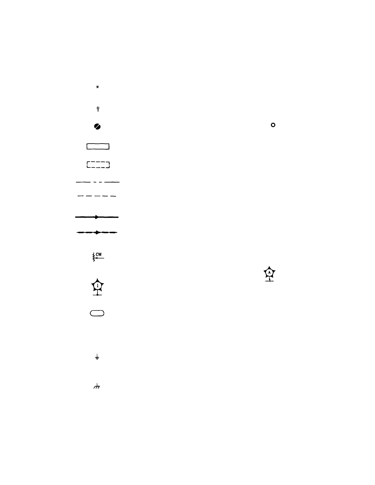
Table 8-4. Schematic Diagram Notes (1 of 3)
Resistance in ohms, capacitance in picofarads,
inductance in microhenries unless otherwise noted.
Asterisk denotes a factory-selected value. Value shown
is typical. Part might be omitted. See Table 5-1.
See Backdating, Tables 7-1 and 7-2.
Tool-aided adjustment. Manual control.
Encloses front-panel designation.
Encloses rear-panel designation.
Circuit assembly borderline.
Other assembly borderline. Also used to indicate
mechanical interconnection (ganging) and RF shielding.
Heavy line with arrows indicates path and direction of
main signal.
Heavy dashed line with arrows indicates path and
direction of main feedback.
Wiper moves toward CW with clockwise rotation of
control (as viewed from shaft or knob).
Numbered Test point. Lettered Test Point. No
Measurement aid measurement aid
(metal post, provided.
circuit pad, etc.) provided.
Encloses wire color code. Code used is the same as the
resistor color code. First number identifies the base
color, second number identifies the wider stripe, third
number identifies the narrower stripe. E.g., ( denotes
white base, yellow wide stripe, violet narrow stripe.
A direct conducting connection to the earth, or a
conducting connection to a structure that has a similar
function (e.g., the frame of an air, sea, or land vehicle).
A conducting connection to a chassis or frame.
Artisan Technology Group - Quality Instrumentation ... Guaranteed | (888) 88-SOURCE | www.artisantg.com