Model 8640B TM 9-4935-601-14-7&P
SERVICE,SHEET 1 (Cont'd)
NOTE
The last two foldouts in this manual have top and bottom internal views of the instrument that show the locations of the test points,
assemblies, and cables (all RF cables are accessible from the bottom of the instrument).
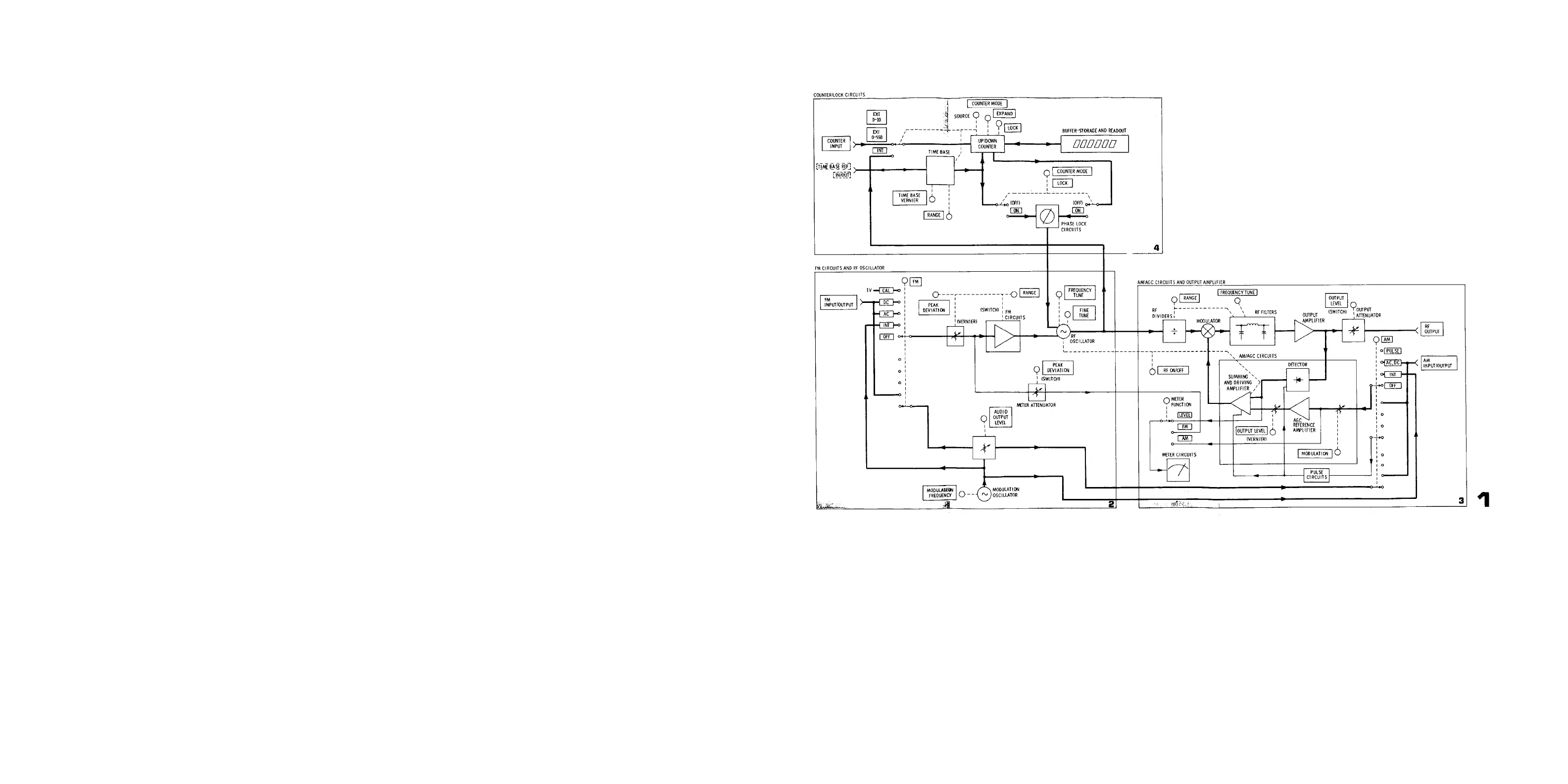
The blocks on Service Sheet 3 are keyed, by the numbers located in their lower right-hand comers, to the Service Sheets that have the circuit schematics. In our
example, suppose the signals to the A26A3 Assembly are correct and the signals from A26A3 are incorrect. Turn to Service Sheet 12 and isolate the trouble to a
component or replace A26A3.
NOTE
After repairs are complete, see Table 5-2 for appropriate post-repair tests and adjustments.
WARNING
The opening of covers or removal of parts, except those to which access can be gained by hand, is likely to expose live parts, and also accessible terminals may be
live. Any adjustment, maintenance, and repair of the opened instrument under voltage should be avoided as much as possible and, if inevitable, should be carried
out only by a skilled person who is aware of the hazard involved.
Capacitors inside the instrument may still be charged even if the instrument has been disconnected from its source of supply.
Make sure that only fuses with the required rated current and of the specified type (normal blow, time delay, etc.) are used for replacement. The use of repaired
fuses and the short-circuiting of fuseholders must be avoided.
Whenever it is likely that the protection has been impaired, the instrument must be made inoperative and be secured against any unintended operation.
Figure 8-16. Overall Block Diagram
8-19
Artisan Technology Group - Quality Instrumentation ... Guaranteed | (888) 88-SOURCE | www.artisantg.com