Model 8640B TM 9-4935-601-14-7&P
CHANGE 19 (Cont'd)
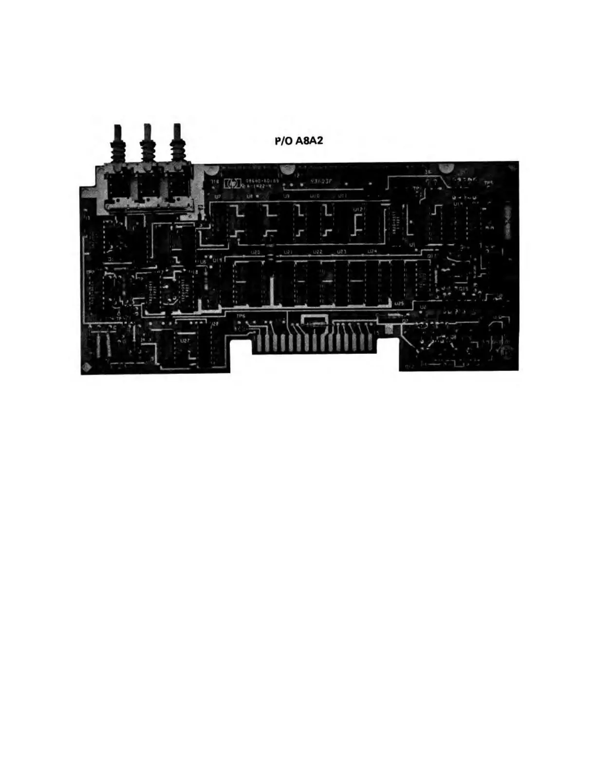
Service Sheet 21 (component locations):
Replace Figure 8-63 with attached figure.
Figure 8-63. P/O A8A2 Counter/Lock Board Assembly Component Locations (P/O Change 19)
Service Sheet 21 (schematic):
Change part number for A8A2 subassembly to 08640-60189.
Service Sheet 22 (Principles of Operation):
Change the second paragraph under Input Voltage (A12 and A14) to read as follows:
The A12 Rectifier Assembly contains five full-wave rectifiers and a crowbar to protect the instrument from
excessively high line voltages. The crowbar is across the output of the rectifier bridge to the +44.6V
regulator. If the rectified voltage exceeds 75V, breakdown diode A12VR1 conducts and triggers the gate of
SCR A12Q1. Q1 then conducts and blows the primary fuse. Diode A12CR21 prevents filter capacitor C3
from discharging through the crowbar when the crowbar conducts.
7-47
Artisan Technology Group - Quality Instrumentation ... Guaranteed | (888) 88-SOURCE | www.artisantg.com