Model 8640B TM 9-4935-601-14-7&P
CHANGE 9
Page 5-28, paragraph 5-38:
Delete step 7.
Page 6-7, Table 6-3:
Change A3A4 to 08640-60196.
Delete A3A4C1, and C2.
Change A3A4R3 to 2100-3123 RESISTOR: VAR: TRMR: 500 OHM 10% C.
Delete A3A4R5.
Change A3A4R7 to 0698-3439 RESISTOR: FXD: 178 OHM 1%0.125 W F TUBULAR.
Change A3A4R8 to 0757-0416 RESISTOR: FXD; 511 OHM 1% 0.125 F.
Delete A3A4U1.
Page 6-15, Table 6-3:
Change A8A2U14 to 1820-0205.
Service Sheet 5 (schematic):
Change the part number for the A3A4 sub-assembly to 08640-60196.
Service Sheet 6 (Principles of Operation):
Input and Buffer Circuits (A5):
Change the seventh sentence to read as follows:
"The gain compensation adjustment potentiometers (A3A4R2, R3, and R4) set the FM sensitivity at the
frequency mid-point and extremes."
Service Sheet 6 (Troubleshooting):
Delete FM Gain Compensation, (A3A4) Circuit.
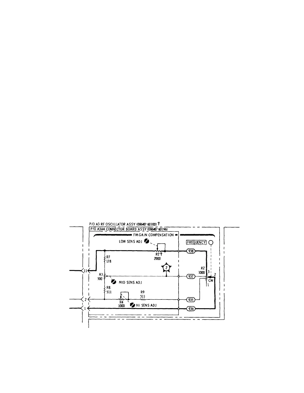
Service Sheet 6 (schematic):
Replace appropriate portion of schematic with the attached partial schematic.
P/O Figure 8-25. FM Amplifiers Schematic Diagram (P/O Change 9).
7-29
Artisan Technology Group - Quality Instrumentation ... Guaranteed | (888) 88-SOURCE | www.artisantg.com