TM 9-4935-601-14-7&P
Model 8640B
CHANGE 34 (Cont'd)
Pages 6-14 and 6-15, Table 6-3 (cont'd):
Change A8A2R17, 0698-7277, RESISTOR, FXD 51.1K 2% 0.05W F TC=0±100
Change ASA2R19, 0698-7270, RESISTOR, FXD 26.1K 2% 0.05W F TC=0±100
Delete A8A2R58
Add A8A2R59, 0698-7281, RESISTOR, FXD 75K 2% 0.05W F TC=0±100
Add A8A2R60, 0698-7188, RESISTOR, FXD 10 2% 0.05W F'TC=0±100
Add ASA2R61, 0698-7243, RESISTOR, FXD 1.96K 2% 0.05W F TC=0±100
Add A8A2R62, 0698-0090, RESISTOR, FXD 464 1% 0.5W F TC=0±100
Service Sheet 7 (schematic):
Change A7R28 to 100K
Change A7R45 to 26.1K
NOTE
For instruments with serial prefixes below 1552A, the recommended replacement for A7R28 is
0757-0465 and for A7R45 is 06983159.
For instruments not already modified as above, it will be necessary to replace both A7R28 and
A7R45 the first time that either resistor is replaced.
Service Sheet 20 (Component Locations):
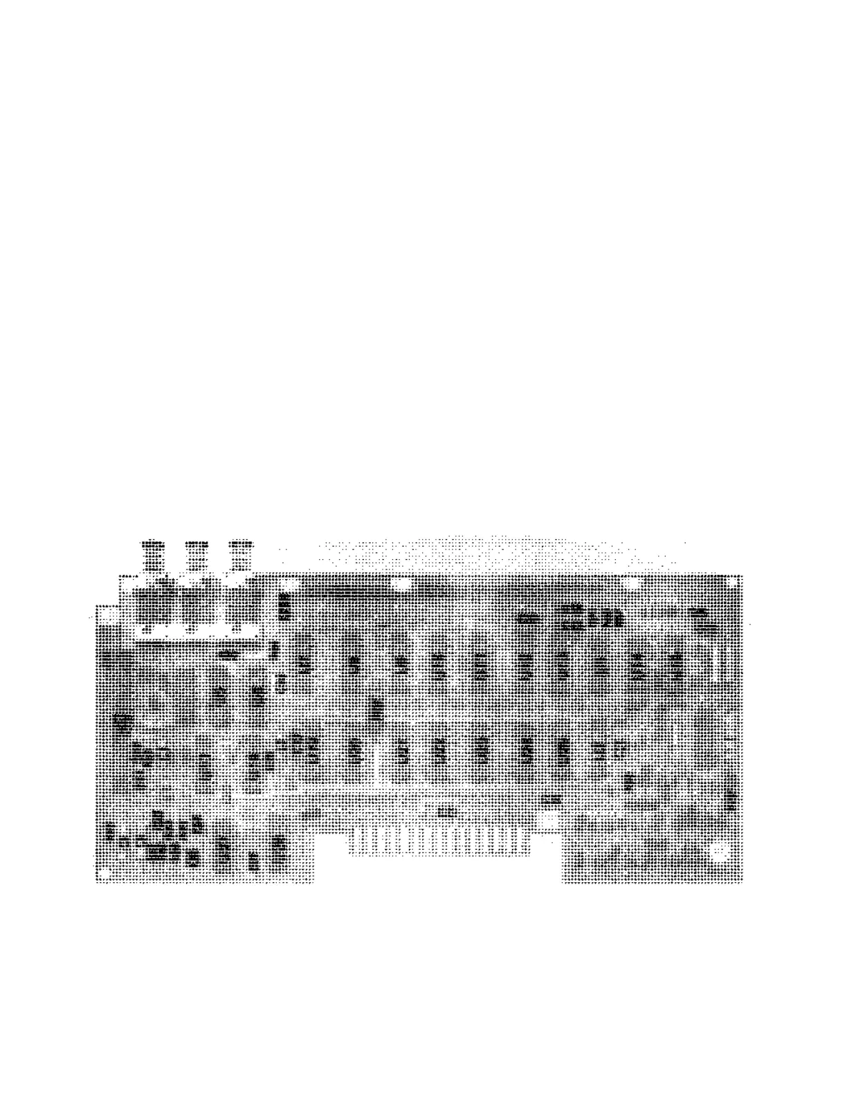
Replace Figure 8-61 with attached figure.
P/O A8A2 ASSEMBLY
Figure 8-61. /0O A8A2 Counter/Lock Board Assembly, Component Locations (P/O Change 34).
Service Sheet 20 (Schematic):
Change A8A2C12 to 300 pF.
Delete the line between A8A2U16B pins 4 and 5.
Add a line from A8A2U16B pin 4 to +5.2V.
7-76
Artisan Technology Group - Quality Instrumentation ... Guaranteed | (888) 88-SOURCE | www.artisantg.com