Model 8640B TM 9-4935-601-14-7&P Model 8640B TM 9-4935-601-14-7&P
SERVICE SHEET 8
PRINCIPLES OF OPERATION
Over-Deviation Detector (A7)
If the FM input signal is too large for the FM circuits to operate properly, the
Over-Deviation Detector lights the REDUCE FM VERNIER annunciator lamp
A6DS1. Integrated circuit U2 is a dual comparator amplifier with wired-OR
outputs. Pin 7 of U2B is at 1.1 Vdc; pin 4 of U2A is at -1.1 Vdc; these two
voltages are the high and low reference voltages. Pins 6 and 3 of U2 are the
common inputs. If the input, which comes from the FM buffer amplifier, is not
between +1.1 and -1.1V, the outputs go high (>1V). Integrated circuit U3 is a
hex inverter with open collector outputs. U3A inverts the comparator output.
When U3A goes low, capacitor C13 is discharged; when U3A goes high again,
C13 slowly charges through R76. This effectively increases the duration of the
comparator output when overloading occurs only for short periods. U3B
inverts the output of U3A and drives four parallel inverters U3C to U3F. When
the outputs of the four parallel inverters are low, the display lamp turns on,
which occurs whenever the input to U3B is low.
Peak Deviation Switch (A9)
The Meter Attenuator scales the FM input signal to give the correct reading on
the meter.
The Scale/Annunciator Lamp Control section of the switch lights the proper
scale annunciator lamp (on A6) for a given peak deviation range when the
meter mode selected is FM.
TROUBLESHOOTING
It is assumed that a problem has been isolated to the over-deviation detector,
meter attenuator, or scale/annunciator lamp control circuits as a result of using
the troubleshooting block diagrams.
Test Equipment
Digital Voltmeter ...................................................................HP 3480B/3484A
Oscilloscope..................................................................HP 180A/1801A/1820C
Initial Test Conditions
Bottom cover removed (see Service Sheet F for removal procedure). Extend
A7 FM Shaping Assembly on extender board. Connect AM OUTPUT to FM
INPUT.
Initial Control Settings
AM .............................................................................................................INT
AUDIO OUTPUT LEVEL...............................................................................cw
MODULATION ...........................................................................................ccw
MODULATION FREQUENCY ...................................................400 Hz (Fixed)
FM ..............................................................................................................AC
PEAK DEVIATION...................................................................................5 kHz
PEAK DEVIATION Vernier .........................................................................ccw
RANGE ..........................................................................................0.5 - 1 MHz
SERVICE SHEET 8 (Cont'd)
Over-Deviation and Meter Control Circuits Troubleshooting
Component Test Conditions and Normal Indication If Indication
or Circuit Control Settings is Abnormal
OVER- Initial conditions REDUCE FM Replace faulty
DEVIATION and settings. Ad- VERNIER lamp component
DETECTOR just PEAK DEVI- unlit and
(A7) ATION vernier for 1. pins 6, 8, 10,
1.8 Vp-p at U2 12 high
pins 3 and 6. 2. U3B pin 4 low
3. U3A pin 2-high
4. TP4 (FM OVER-
LOAD) low
Adjust PEAK REDUCE FM Replace faulty com-
DEVIATION VERNIER lamp ponent
vernier for 2.4 lit and
V p-p at U2 1. pins 6, 8, 10,
pins 3 and 6 12 low
2. U3B pin 4 high
3. U3A pin 2 low
4. TP4 (FM OVER-
LOAD) >2 Vp-p
SCALE/ Initial conditions SCALE lamps light Check scale lamps
ANNUNCI- and settings. Set as follows: (A6) and switches
ATOR Meter Function to (A9)
LAMP FM and set
CONTROL PEAK DEVIA-
(A9) TION as follows:
5 kHz 5
10 kHz 10
20 kHz 3
40 kHz 5
80 kHz 10
160 kHz 3
320 kHz 3
640 kHz 10
1.28 MHz 3
2.56 MHz 3
5.12 MHz 5
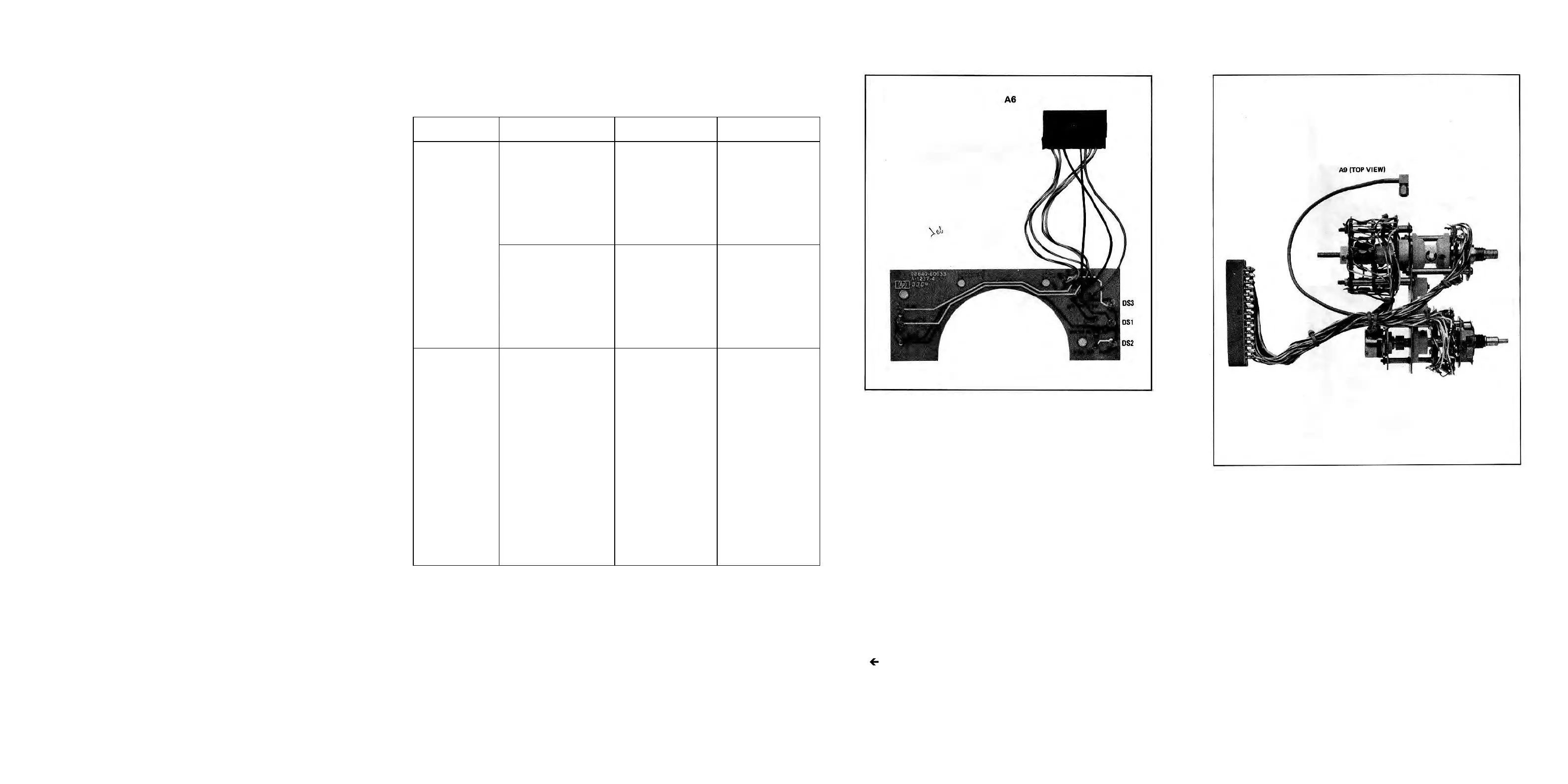
Figure 8-28. P.O A6 Annunciator Assembly Component
Locations.
FM Shaping Circuits and Phase Lock Loop Filter (A7, A9)
SERVICE SHEET 7
8-32
Figure 8-29. P/O A9 Peak Deviation and Range Switch Assembly
Component Locations (1 of 2).
Artisan Technology Group - Quality Instrumentation ... Guaranteed | (888) 88-SOURCE | www.artisantg.com