Model 8640B TM 9-4935-601-14-7&P
SETTING MODULATION
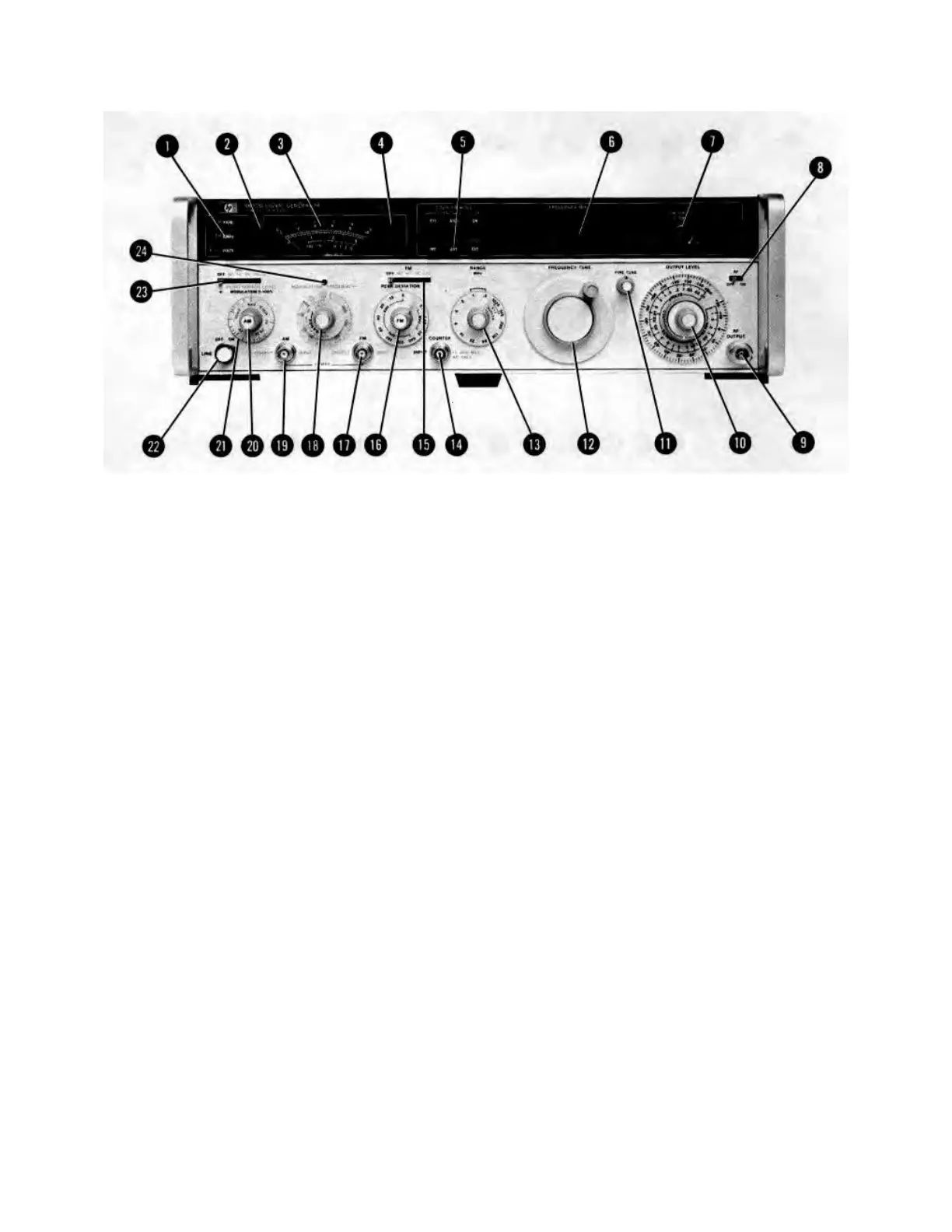
d. To use an external modulation signal, set AM (23) to AC (or DC if modulation signal is less than 20 Hz). Apply
the signal to the AM INPUT jack (19) (600 ohm load impedance). The Signal Generator requires 1 Vpk (0.7071
Vrms) for 100% modulation. Set percent of modulation with the MODULATION vernier (20) ; % AM is indicated
by the meter (3).
NOTE
The meter reading is accurate when AM is set to DC only if no dc offset is applied to the AM
INPUT jack. The meter responds to the positive peak of the ac component of the modulating
signal.
Pulse Modulation
a. Set Meter Function (1) to LEVEL.
b. Set AM (23) to PULSE (this disables the RF output). Apply the modulation pulse (>0.5V) to the AM INPUT jack
(19) (50 ohm load impedance). The Signal Generator requires a positive level to produce an RF output.
c. Set the desired pulse-on level using the OUTPUT LEVEL controls (10).
Figure 3-6. Setting the Modulation Controls (2 of 4)
3-16
Artisan Technology Group - Quality Instrumentation ... Guaranteed | (888) 88-SOURCE | www.artisantg.com