Model 8640B TM 9-4935-601-14-7&P
PERFORMANCE TESTS
4-23. OUTPUT LEVEL ACCURACY TEST (Abbreviated) (Cont'd)
2. Set power meter's controls so that it can measure +19 dBm. Connect power sensor to Signal Generator's RF
OUTPUT.
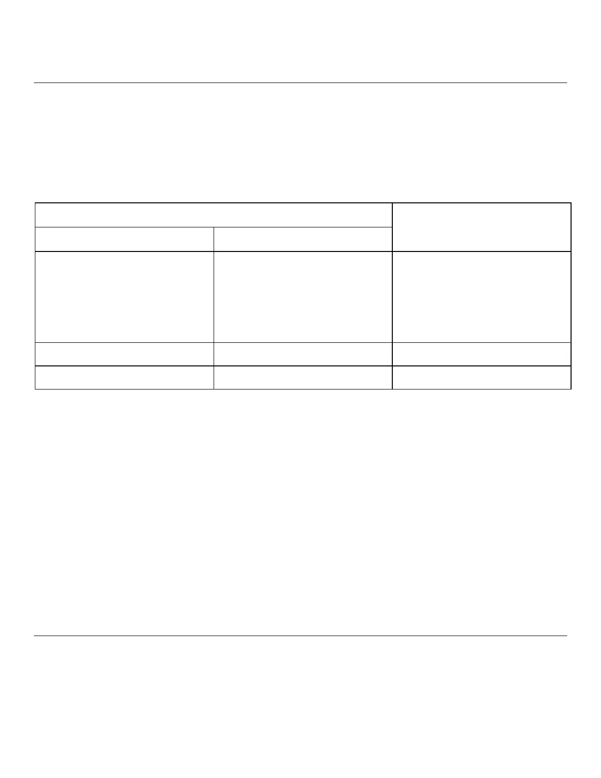
3. Set Signal Generator's RF OUTPUT LEVEL controls for levels (set using generator's panel meter) shown in the
table below; verify that the level is within the specified tolerance.
Signal Generator
Power Meter
OUTPUT LEVEL R F Level Set Reading (dBm)
Switch (with Panel Meter)
Set level
Full cw +19 dBm +17.5 - 20.5
+13 dBm +11.5 - +14.5
+5 dBm +3.0 - +7.0
1 step ccw +13 dBm +11.5 - +14.5
from full cw +8 dBm +6.5 - +9.5
+3 dBm +1.5 - +4.5
-5 dBm -7.0 - -3.0
2 steps ccw +3 dBm +1.5 - +4.5
from full cw
3 steps ccw -7 dBm -8.5 - -5.5
from full cw
4. Set step attenuator to 70 dB. Set spectrum analyzer center frequency to 512 MHz, resolution bandwidth to 1
kHz, frequency span per division (scan width) to 0.5 kHz, input attenuation to 0 dB, tuning stabilizer on, display
smoothing (video filter) to 100 Hz, 2 dB per division vertical log display with a -20 dBm reference level.
5. Connect attenuator to generator's RF OUTPUT without disturbing generator's controls. Center signal on
analyzer's display. Consider the center horizontal graticule line equivalent to -7 dBm (with a panel meter reading
of +3 dB), then with the vertical scale reference vernier control set the signal peak to be equal to the last
measured level on the power meter.
NOTE
If, for example, the last power meter reading was -7.4 dBm, the vertical scale resolution is 2
dB/division, therefore, the signal peak should be 0.4 dB or 0.2 division below the center
(reference) graticule line.
4-26
Artisan Technology Group - Quality Instrumentation ... Guaranteed | (888) 88-SOURCE | www.artisantg.com