C-2 Preliminary November 4, 1998 MAX 4000 Series Hardware Installation Guide
Cables and Connectors
User interface specifications
Pin 9 is not active. (Ring Indication signal not supplied.)
Pinouts for the palmtop-controller
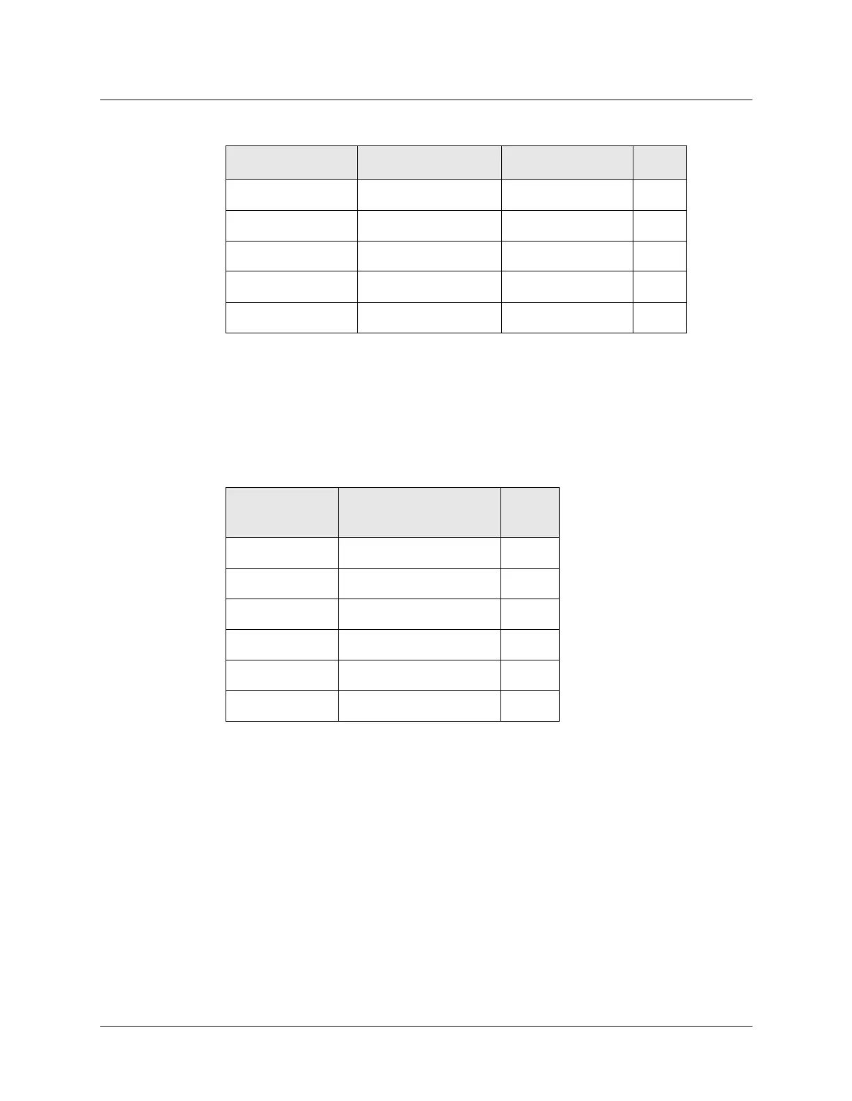
Table C-2 specifies the pins and corresponding functions of the palmtop-controller jacks.
In the I/O column, O (Out) is from the MAX toward the palmtop.
5 GND Signal Ground
6 DSR Data Set Ready O
7 RTS Request to Send I
8 CTS Clear to Send O
*9 *RI *Ring Indicator *O
Table C-1.Control-monitor and MIF control-port and cabling pinouts (continued)
DE-9 pin number RS-232 signal name Function I/O
Table C-2.Palmtop-controller pinouts
MAX RJ–12
pin
Function I/O
1 Power to Palmtop, +5V O
2 Control Out O
3 Control In I
4 Serial Transmit Data O
5 Serial Receive Data I
6 Ground
 Loading...