1-2 Preliminary November 4, 1998 MAX 4000 Series Hardware Installation Guide
Getting Acquainted with the MAX
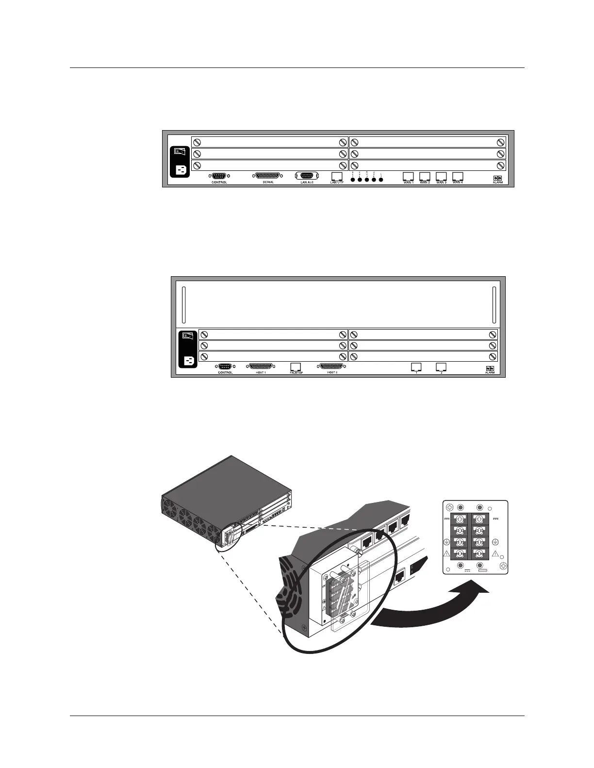
The items in your MAX package
Figure 1-1. MAX base unit
Figure 1-2. Redundant MAX base unit
Figure 1-3. DC power source on the MAX 4000 and the Redundant MAX 4000
CONTROL
PCMCIA
DRAMLAN UTP SERIAL ALARM
WAN
1234
A
C
T
FD
X
LN
K
100B
T
C
O
L
FU
S
E
TY
P
E
R
A
T
E
D
250V
, 2A
RTN
-48
16A 60V
RTN
-48
LAN UTP
CONTROL
RTN
-48
16A 60V
RTN
-48
CONTROL
R
T
N
-48
1
6A 60
V
R
T
N
-4
8
(Shown with clear
plastic guard
removed)
 Loading...