Setting Up and Testing the MAX Hardware
Interpreting the MAX LEDs
MAX 4000 Series Hardware Installation Guide Preliminary November 4, 1998 2-9
Cable length and characteristics
The maximum distance between the E1/PRI WAN interface equipment and the MAX should
not introduce attenuation of more than 6dB, when measured at half the maximum data rate
(1024 Kbps). Also, the cable must have a root F characteristic.
Interpreting the MAX LEDs
Before you start up the MAX, you need to understand the indicator lights (LEDs) on the
number front- and back-panels of the MAX.
MAX front-panel
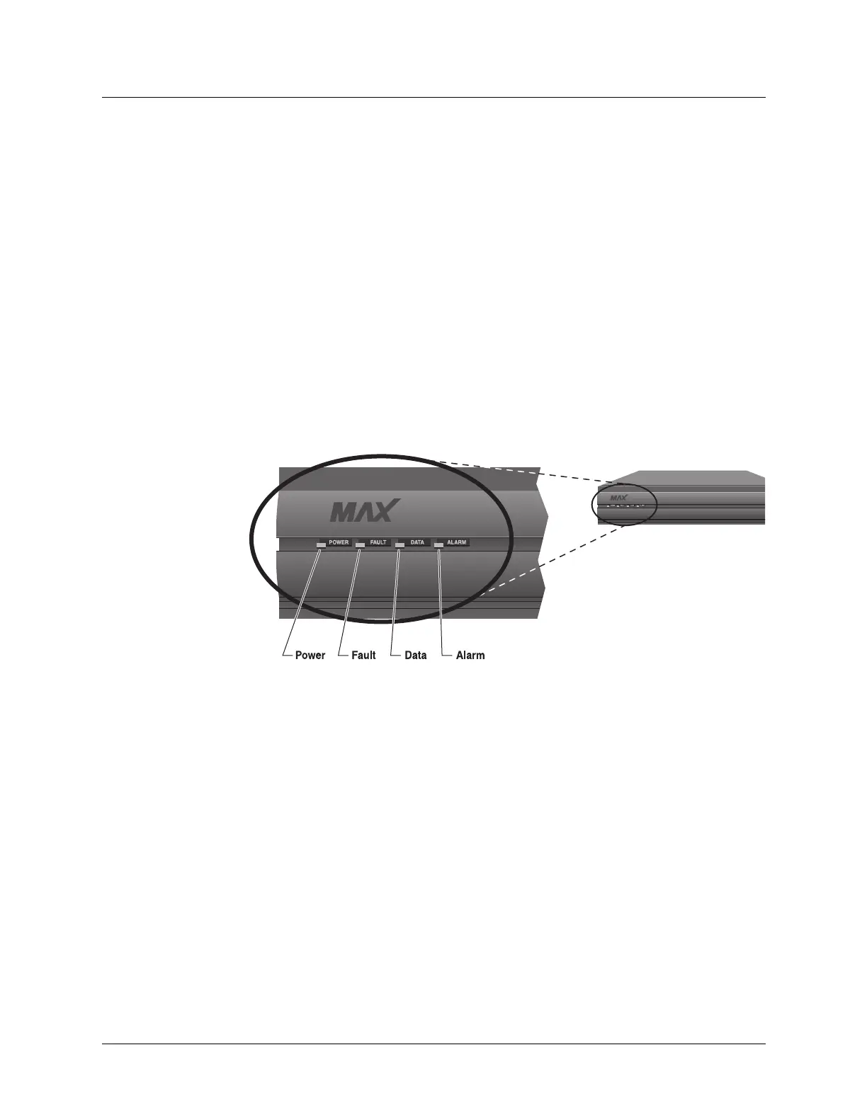
Figure 2-9 shows the location of LEDs on the MAX front-panel, and Figure 2-10 shows the
location of the LEDs on the Redundant MAX front-panel.
Figure 2-9. Location of the MAX LEDs
 Loading...