2-12 Preliminary November 4, 1998 MAX 4000 Series Hardware Installation Guide
Setting Up and Testing the MAX Hardware
Interpreting the MAX LEDs
MAX back-panel
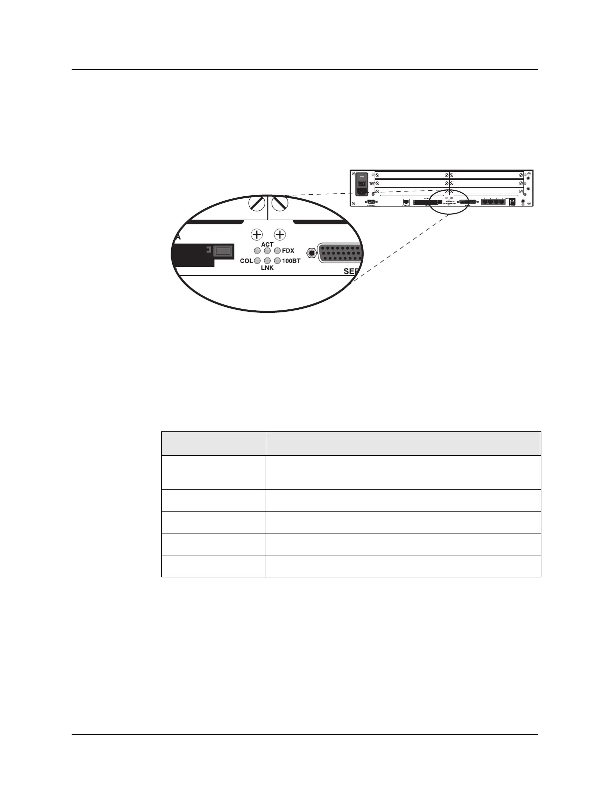
Figure 2-11 shows the MAX back-panel LEDs, which display the status of the Ethernet–
interface.
Figure 2-11. Ethernet interface LEDs on MAX back-panel
Note: The MAX Classic back-panel has similar LEDs on the Ethernet expansion card if one
is installed. The MAX Classic has one LED for each possible Ethernet interface (10Base-T,
and COAX (10Base-2), which illuminate when the interface is in use. The ACT and COL
LEDs are the same as those on the MAX 6000.
Table 2-3 describes the Ethernet-interface LEDs.
Once you are familiar with the MAX LEDs, you are ready to start up the MAX.
Table 2-3. Ethernet-interface LEDs on back-panel
LED Description
ACT (Activity) On when the MAX is detecting activity (network traffic) on its
Ethernet interface.
COL (Collisions) On when the MAX detects packet collisions on the Ethernet.
FDX On indicates full duplex on the Ethernet.
100BT On, indicates 100BT. Off indicates 10BT.
LINK (Link integrity) On when the Ethernet interface is functional.
 Loading...