3-38 Preliminary November 4, 1998 MAX 4000 Series Hardware Installation Guide
Quickstart
Implementing a basic configuration
9 Press the Left-Arrow or Escape key to exit the Ethernet Mod Config profile.
In the confirmation menu, press 2 to save and exit.
You have now set all the parameters necessary for your E1 line configuration.
Check the line’s status
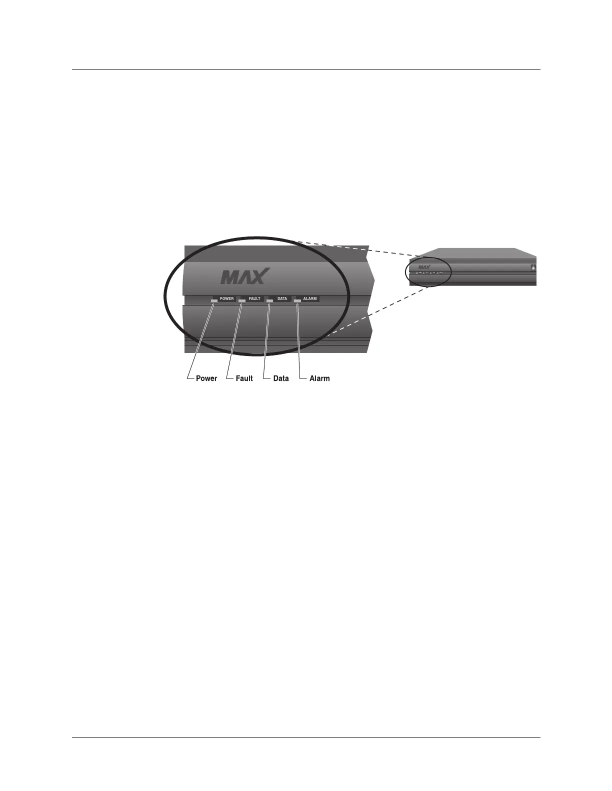
After the E1/PRI provider has established service, observe the MAX unit’s front-panel
indicator lights (LEDs) as illustrated in Figure 3-5.
Figure 3-11. Front-panel indicator lights
Is the Power LED on and are the Fault, Data, and Alarm LEDs off?
• If Yes: Continue on to “Configuring the Ethernet profile.”
• If No: The connection to the E1/PRI line has failed. If the Alarm LED is on, check your
cabling. Also verify with your E1/PRI line provider that you have the correct Framing
Mode, Encoding, Length, and Buildout values.
Re-entering E1 line parameters
If you must re-enter the parameters for your E1 line, make sure you have Full Access
privileges and return all parameter values to their defaults as listed in the following steps:
1 At the Main Edit Menu, press Ctrl-D.
The Main Edit Menu’s DO menu appears.
2 Select P (Password).
3 Press Enter or the Right-Arrow key.
The Security Profile menu appears.
4 Select Full Access.
5 Press Enter or the Right-Arrow key.
A password entry field appears.
6 Enter your password within the brackets.
7 Press Enter or the Right-Arrow key.
If your password is accepted, you have Full Access privileges.
8 Press Enter.
 Loading...