Setting Up and Testing the MAX Hardware
Interpreting the MAX LEDs
MAX 4000 Series Hardware Installation Guide Preliminary November 4, 1998 2-11
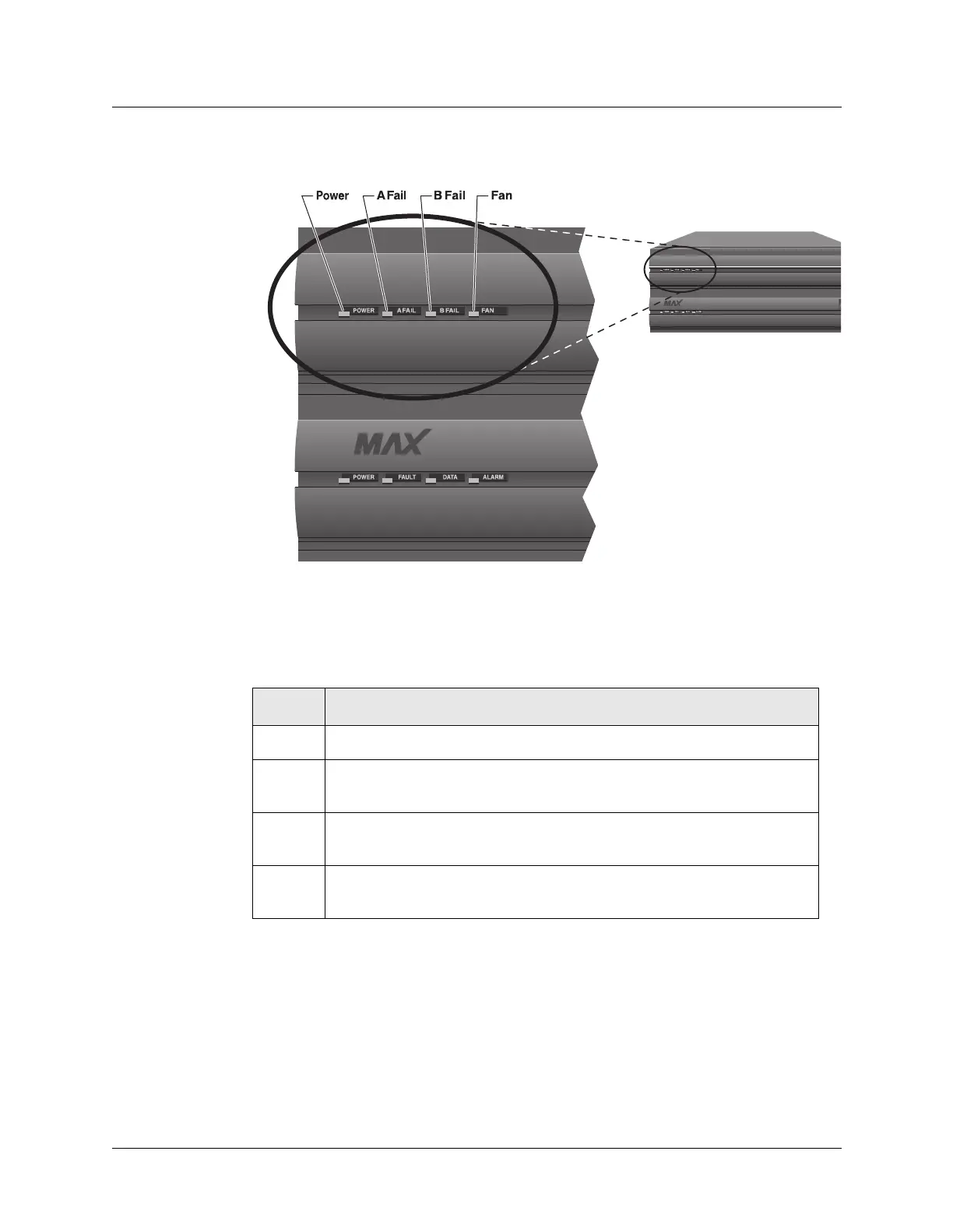
Figure 2-10. Location of the LEDs on the Redundant MAX
Table 2-2 lists and describes each LED on the front-panel of the Redundant MAX. This is
supplemental information for the redundant ac or dc power supply.
Table 2-2. Redundant MAX LEDs
LED Description
Power On when the Redundant MAX power supply is on.
A Fail On only if one or more of the voltages from side A of the power supply
(+12, +5, +3.3, -12, -5) has failed.
B Fail On only if one or more of the voltages from side B of the power supply (+12,
+5, +3.3, -12, -5) has failed.
Fan On when the fans are functioning properly (if +12 VDC from either A or B
is good). This LED goes off in the event of a fan failure.
 Loading...