2-2 Preliminary November 4, 1998 MAX 4000 Series Hardware Installation Guide
Setting Up and Testing the MAX Hardware
Planning the hardware installation
• Or, alternatively, a hand-held palmtop terminal and associated cable less than 10 feet (3
meters) in length.
• A remote Ascend or compatible unit to which you can telnet or which you can Ping over a
dial-up Point-to-Point Protocol (PPP) connection.
• Any expansion modules that were shipped separately.
Guidelines for installing digital modems
• The Series56 architecture requires that all modem modules within a MAX chassis be
homogeneous. That is, Series56 modules must not be mixed with non-Series56 digital
modem modules.
• The Series56 architecture also requires that the modem density be homogeneous. Modem
modules with mixed densities (for example, 8-port and 12-port modem modules) must not
be combined in a single chassis.
• The MAX can support a total of 96 digital modems.
Guidelines for installing MAX units in a rack
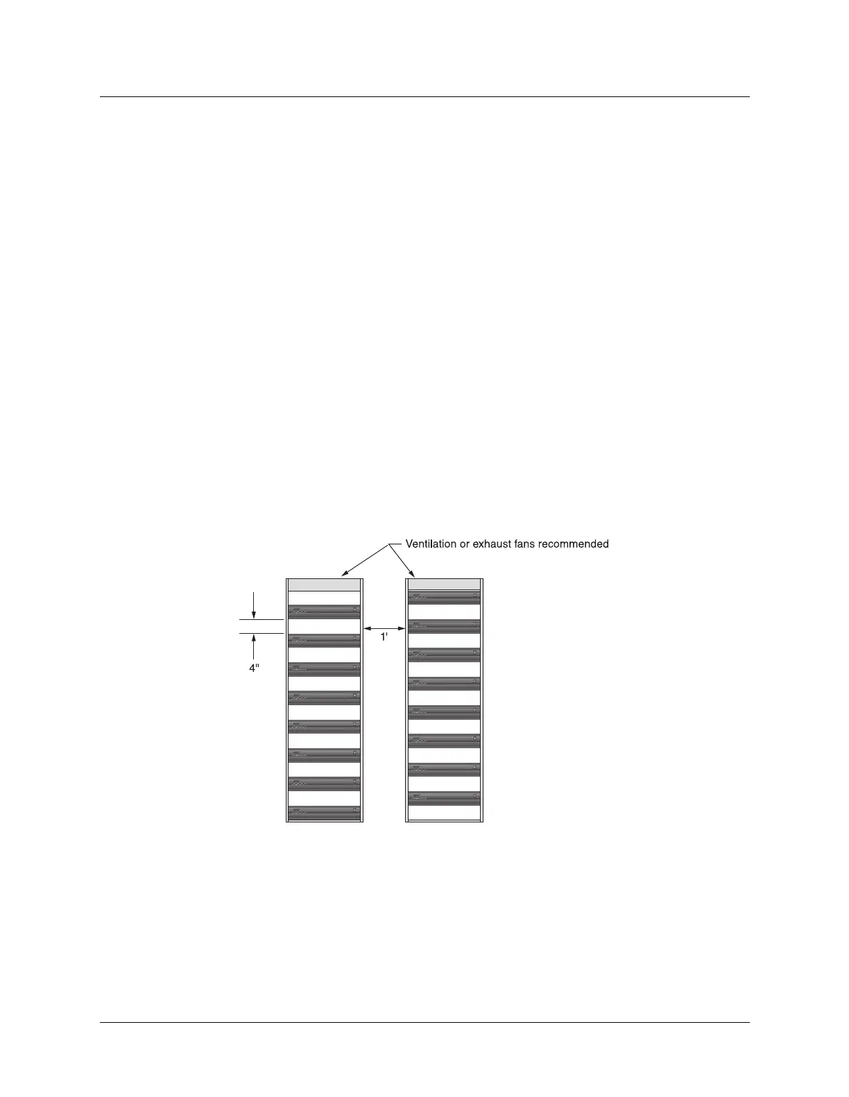
Figure 2-1 shows an example of MAX units installed in a rack.
Figure 2-1. MAX units installed in a rack.
• Leave approximately four inches of vertical space between MAX units to allow adequate
air flow and leave room for handling the units if they need to be removed.
• Leave approximately one foot between the racks of MAX units for adequate air flow.
• Stair-step MAX units in adjacent open racks, so that hot air from one unit is not being
blown into an adjacent unit. The intake fans are on the right (as viewed from the front),
and the exhaust fans are on the left.
• Ensure adequate cooling in the room.
 Loading...