TD 92372GB
2007-06-18/ Ver. E
Installation and Operation Manual
IP-DECT Base Station & IP-DECT Gateway
17
Pin the IPBS Cable
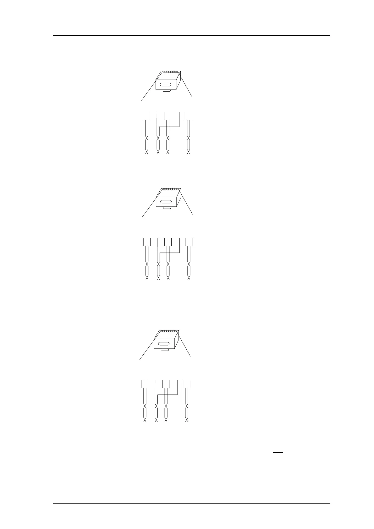
Figure 21.
RJ45
modular jack
Tx
Tx
Rx
Pwr
Pwr
Rx
Pwr
Pwr
Pwr = Power pairs
Rx = Reciever data pair
Tx = Transmitter data pair
014
15432678
Figure 7. Connector pinning of the LAN/PoE connector, power feed over the spare
cable pairs.
Figure 22.
RJ45
modular jack
Tx/Pwr
Tx/Pwr
Rx/Pwr
Spare
Spare
Rx/Pwr
Spare
Spare
NC
=
Not Connected
Rx/Pwr
=
Reciever & power pair
Tx/Pwr = Transmitter & power pair
015
15432678
Figure 8. Connector pinning of the LAN/PoE connector, power feed over the Rx/Tx
data cable pairs.
Pin the BS3x0 Cable
Figure 23.
RJ45
modular jack
EPP-b
EPP-a
SC1-a
SC0-a
SC0-b
SC1-b
NC
NC
NC
=
Not Connected
EPP
=
Express Power Pairs
SC = Serial Channel
008
15432678
Figure 9. Connector pinning of the Data connector
IMPORTANT: If local power supply is used, the EPP cable pair must not be connected.