TD 92372GB
2007-06-18/ Ver. E
Installation and Operation Manual
IP-DECT Base Station & IP-DECT Gateway
24
5.3.2 48 VDC
The 48 VDC (42 – 56 VDC) power input includes a fuse on the 48 VDC input to protect
against overload. The IPBL also has a protection circuit to protect both the IPBL and the
external power supply from damages caused by the user reversing the input terminals
during installation.
Figure 32.
12
3
034
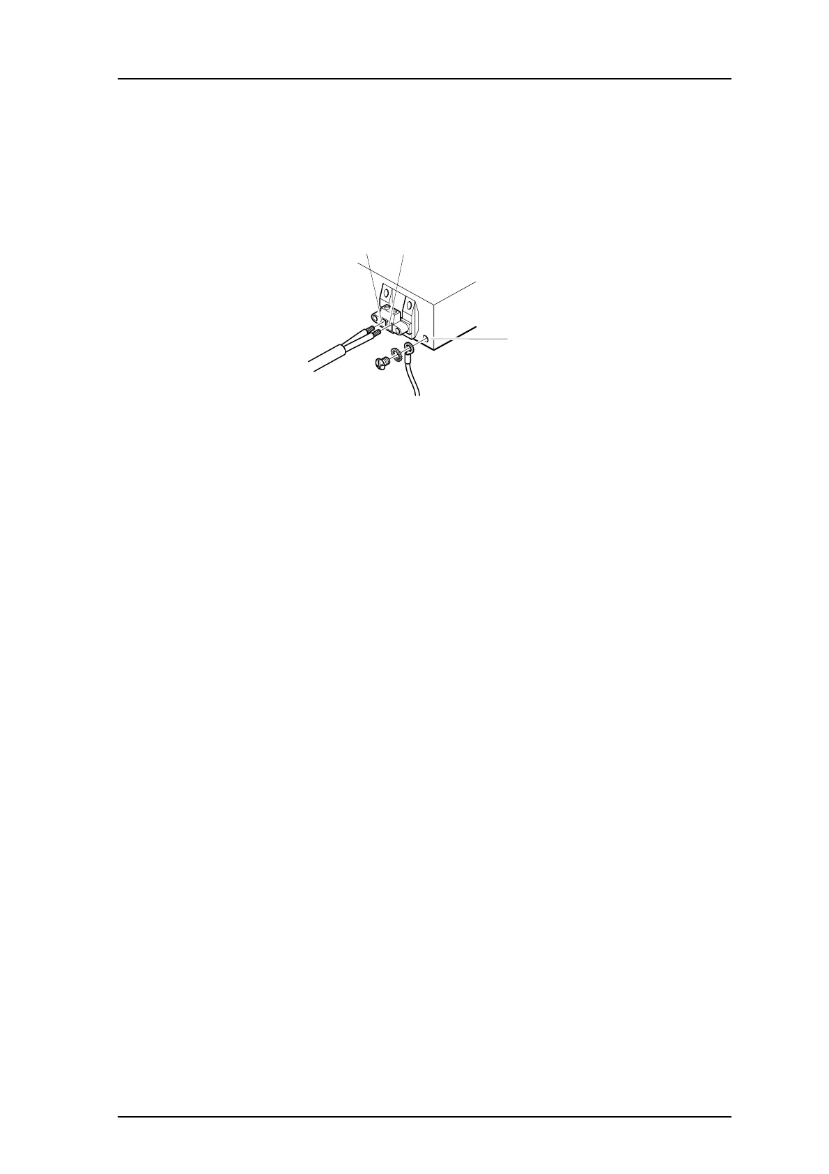
Figure 18. Pinning of the 48 VDC power supply
Note: An ground cable must be fastened to the protective earth (3) when 48 VDC is used
as power source.
1 Fasten the ground cable to the protective earth (3) using the attached M4 screw
(Philips) and washer.
2 Cut the power cable to the correct length.
3 Attach the positive lead to (1).
4 Attach the negative lead to (2).
5 Connect the power cable to 48 VDC power source.
The IPBL is switched on.
6 Configuration
This section describes how to configure the IPBS and IPBL using the web interface. The
recommended order to configure the equipment in the IP-DECT system is as follows:
1 Configure the master, see 6.3 Configure the Master on page 27.
2 Configure the standby master, see 6.4 Configure the Standby Master on page 28.
3 Configure the slaves, see 6.5 Configure the Slave on page 29.
6.1 Requirements
The following is required in order to configure the IP-DECT system:
•PC
• 10/100base-T Ethernet connection
6.1.1 Web Browser Requirements
To use the interface properly, the web browser has to meet the following requirements: