TD 92372GB
2007-06-18/ Ver. E
Installation and Operation Manual
IP-DECT Base Station & IP-DECT Gateway
23
5.3 Power the IPBL
The IPBL power supply connectors are located at the rear. The power supply feeds both
the IPBL and the connected RFPs. There are two alternatives to power the IPBL:
• 110/230 VAC, 60/50 Hz
• 48 VDC
5.3.1 110/230 VAC
The 110/230VAC (100 – 240 VAC) power input is protected against overload by a fuse.
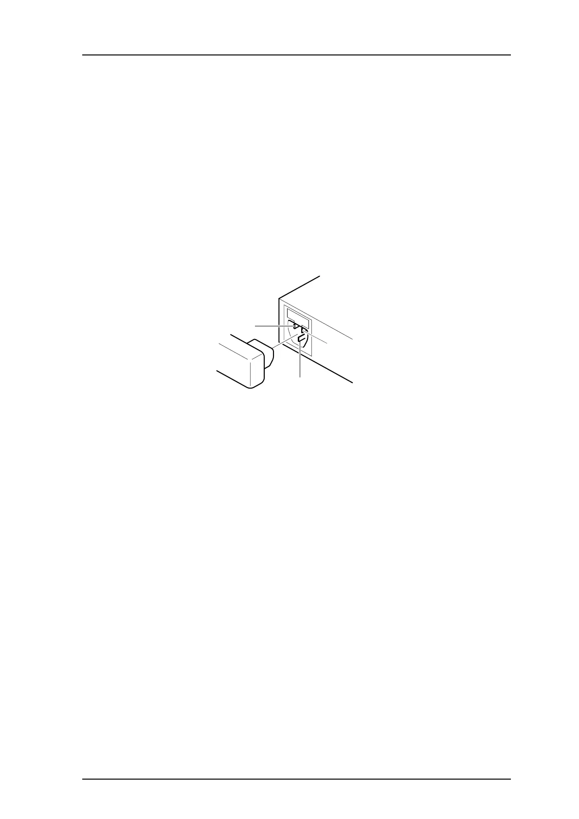
The IEC 60320 type C14 (male) connector consists of:
• live lead (1)
• neutral lead (2)
• protective earth (3)
Figure 31.
1
2
3
010
Figure 17. Pinning of the 110/230 VAC power supply
1 Connect the power cable on the IPBL.
2 Connect the power cable in a wall socket with protected earth.
The IPBL is switched on.