TD 92372GB
2007-06-18/ Ver. E
Installation and Operation Manual
IP-DECT Base Station & IP-DECT Gateway
20
Figure 26.
lan synchronization reference
1 2 ring in ring out in out
base station 01 02 03 04 05 06 07 08
09 10 11 12 13 14 15 16
009
{
{
{
1
23
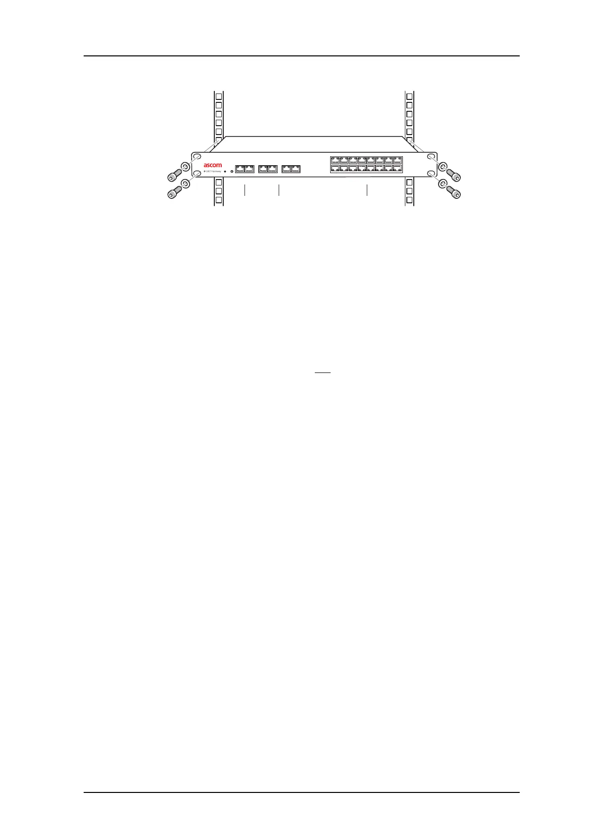
Figure 12. Install the IPBL
The main steps of the installation is described below:
1 Install the IPBL in a standard 19’’ rack.
2 Pin the cables, see 5.2 Pin the IPBL Cable on page 21.
3 Connect the cables in the following order:
• Ethernet cable (1)
• Synchronization cable (sync ring, reference sync) (2)
• Base station cable (RFP cable) (3)
IMPORTANT: The connected RFPs must not be connected to protective earth.
4 Attach the power cable, see 5.3 Power the IPBL on page 23.
5 Monitor the total current consumption from the GUI. See 7.11.5 Environment on
page 59. Make sure it not exceeds the following values:
• Max current consumption is 4,0 A when supplied with 110/230 VAC.
• Max current consumption is 5,2 A when supplied with 48 VDC.
Note: The IPBL current consumption is 0,3 A and is included in max current
consumption.
For more information of power consumption of the RFPs, see Appendix B: RFP
Power Consumption on page 69.