147
7647H–AVR–03/12
Atmel ATmega16/32/64/M1/C1
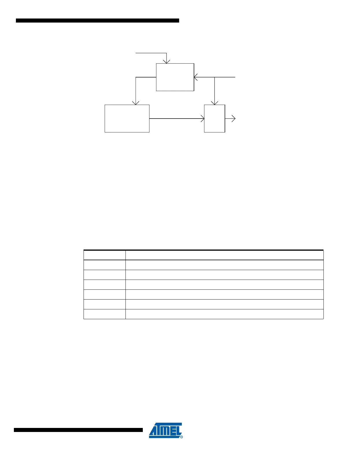
Figure 14-11. PSC Input Filterring
14.9.1.2 Signal Polarity
One can select the active edge (edge modes) or the active level (level modes) See PELEVnx bit
description in Section "PSC Module n Input Control Register – PMICn", page 155.
If PELEVnx bit set, the significant edge of PSCn Input A or B is rising (edge modes) or the active
level is high (level modes) and vice versa for unset/falling/low
• In 2- or 4-ramp mode, PSCn Input A is taken into account only during Dead-Time0 and
On-Time0 period (respectively Dead-Time1 and On-Time1 for PSCn Input B).
• In 1-ramp-mode PSC Input A or PSC Input B act on the whole ramp.
14.9.1.3 Input Mode Operation
Thanks to 4 configuration bits (PRFM3:0), it’s possible to define the mode of the PSC inputs.
Table 14-5. PSC Input Mode Operation
Notice: All following examples are given with rising edge or high level active inputs.
Digital
Filter
4 x CLK
PSC Input
Module X
Ouput
Stage
PSCOUTnX
PIN
PSC Module n Input
CLK
PSC
PSC
PRFMn2:0 Description
000b No action, PSC Input is ignored
001b Disactivate module n Outputs A
010b Disactivate module n Output B
011b Disactivate module n Output A & B
10x Disactivate all PSC Output
11xb Halt PSC and Wait for Software Action