185
7647H–AVR–03/12
Atmel ATmega16/32/64/M1/C1
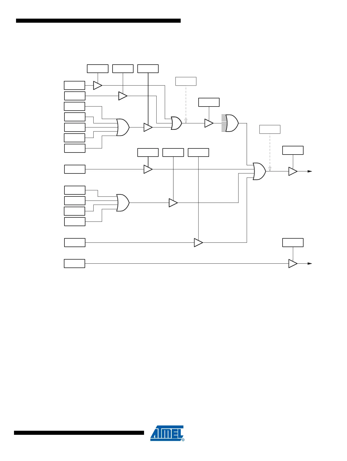
Figure 16-14. CAN Controller Interrupt Structure
16.8.2 Interrupt Behavior
When an interrupt occurs, an interrupt flag bit is set in the corresponding MOb-CANSTMOB reg-
ister or in the general CANGIT register. If in the CANIE register, ENRX / ENTX / ENERR bit are
set, then the corresponding MOb bit is set in the CANSITn register.
To acknowledge a MOb interrupt, the corresponding bits of CANSTMOB register (RXOK,
TXOK,...) must be cleared by the software application. This operation needs a read-modify-write
software routine.
To acknowledge a general interrupt, the corresponding bits of CANGIT register (BXOK, BOF-
FIT,...) must be cleared by the software application. This operation is made writing a logical one
in these interrupt flags (writing a logical zero doesn’t change the interrupt flag value).
OVRTIM interrupt flag is reset as the other interrupt sources of CANGIT register and is also
reset entering in its dedicated interrupt handler.
When the CAN node is in transmission and detects a Form Error in its frame, a bit Error will also
be raised. Consequently, two consecutive interrupts can occur, both due to the same error.
When a MOb error occurs and is set in its own CANSTMOB register, no general error is set in
CANGIT register.
TXOK[i]CANSTMOB.6
RXOK[i]CANSTMOB.5
BERR[i]CANSTMOB.4
SERR[i]CANSTMOB.3
CERR[i]CANSTMOB.2
FERR[i]CANSTMOB.1
AERR[i]CANSTMOB.0
BXOKCANGIT.4
SERGCANGIT.3
CERGCANGIT.2
FERGCANGIT.1
AERGCANGIT.0
BOFFICANGIT.6
ENTX
CANGIE.4
ENRX
CANGIE.5
ENERR
CANGIE.3
ENBX
CANGIE.2
ENERG
CANGIE.1
ENBOFF
CANGIE.6
IEMOB[i]
CANIE 1/2
ENIT
CANGIE.7
ENOVRT
CANGIE.0
SIT[i]
CANSIT 1/2
CANIT
CANGIT.7
CAN IT
OVR IT
0
i
OVRTIMCANGIT.5
 Loading...


