47
7647H–AVR–03/12
Atmel ATmega16/32/64/M1/C1
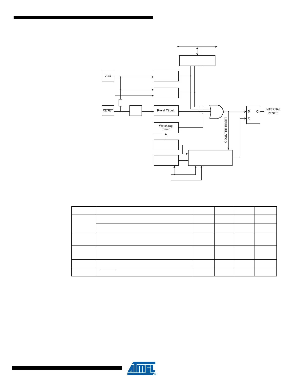
Figure 7-1. Reset Logic
Note: 1. Before rising, the supply has to be between V
PORMIN
and V
PORMAX
to ensure a Reset.
7.2.1 Power-on Reset
A Power-on Reset (POR) pulse is generated by an On-chip detection circuit. The detection level
is defined in Table 7-1. The POR is activated whenever V
CC
is below the detection level. The
POR circuit can be used to trigger the start-up Reset, as well as to detect a failure in supply
voltage.
A Power-on Reset (POR) circuit ensures that the device is reset from Power-on. Reaching the
Power-on Reset threshold voltage invokes the delay counter, which determines how long the
device is kept in RESET after V
CC
rise. The RESET signal is activated again, without any delay,
when V
CC
decreases below the detection level.
Table 7-1. Reset Characteristics
Symbol Parameter Min Typ Max Units
V
POT
Power-on Reset Threshold Voltage (rising) 1.1 1.4 1.7 V
Power-on Reset Threshold Voltage (falling)
(1)
0.8 0.9 1.6 V
V
PORMAX
VCC Max. start voltage to ensure internal
Power-on Reset signal
0.4 V
V
PORMIN
VCC Min. start voltage to ensure internal
Power-on Reset signal
-0.1 V
V
CCRR
VCC Rise Rate to ensure Power-on Reset 0.01 V/ms
V
RST
RESET Pin Threshold Voltage 0.1 V
CC
0.9V
CC
V
MCU Status
Register (MCUSR)
Brown-out
Reset Circuit
BODLEVEL [2..0]
Delay Counters
CKSEL[3:0]
CK
TIMEOUT
WDRF
BORF
EXTRF
PORF
DATA BUS
Clock
Generator
Spike
Filter
Pull-up Resistor
Watchdog
Oscillator
SUT[1:0]
Power-on Reset
Circuit