Home
Autronica
Smoke Alarm
Autro Safe
Page 32 (Connecting Internal Cables)
Autronica Autro Safe - Connecting Internal Cables; Overview - BS-420; BC-420
88 pages
Manual
Save Page as PDF
To Next Page
To Next Page
To Previous Page
To Previous Page
Loading...
Connecti
ng Int
ernal C
ables
Installat
ion H
andbook
,
A
utroS
afe I
nteracti
ve Fir
e Detecti
on Sy
stem, R
elease
4,
116
-P-
ASA
FE
-
INSTALL/DGB
Rev. I,
2014
-
04
-
01
,
Autronica
Fire
and Sec
urity A
S
Page 32
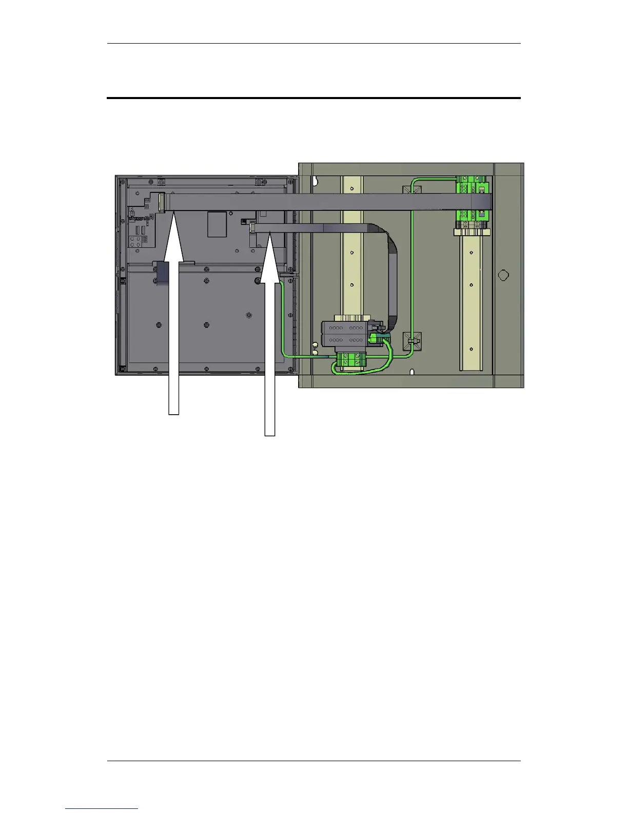
8.
Connec
ting Inte
rnal Cable
s
8.1
O
ve
r
view
– BS-420 / BC
-420
Multifunc
tion cab
le
XGE
-
1/20
-
40
AL_Com
+ cable
XGE
-
1/10
-
50
31
33
Table of Contents
Main Page
Default Chapter
3
Table of Contents
3
Autronica Fire and Security as Page
3
Autronica Fire and Security as Page
4
Autronica Fire and Security as Page
5
Autronica Fire and Security as Page
6
1 Introduction
7
About the Handbook
7
The Reader
7
Reference Documentation
8
2 Pre-Installation
9
Location
9
Environmental Requirements
9
Mounting Height / Space Requirement
9
3 System Units - Overview
10
4 Loop Panels - Overview
13
5 Mounting Instructions
14
Introduction
14
Mounting Fire Alarm Control Panel BS-420 / Controller BC-420
15
Mounting the Operator Panel BS-430
17
Mounting Repeater Panel BU-BV-420
18
Mounting Loop Panels (BV-110 and BU-110)
20
Mounting Power Cabinet BP-405
21
Mounting Power Supply Unit BPS-405 / BPS-410
24
Inserting Text Foils
25
Cable Inlets / Outlets
26
Cut out Dimensions for Flush Mounting in a Wall
27
Repeater Panel BU-BV-420
27
Operator Panel BS-430
28
6 Power Consumption
29
Mains Power
29
Bps-405
29
Bps-410
29
System Units
29
Loop Units
29
Phoenix Ethernet Switches
30
Power Design Considerations
30
7 Cable Connection Overview
31
8 Connecting Internal Cables
32
Overview - BS-420 / BC-420
32
Bs-420 / Bc-420
33
Al_Com+ Connection on Controller Board BSA-400
33
Al_Com+ Connection on Communication Module BSL-310
33
Multifunction Serial Port Connection on Controller Board BSA-400
34
Multifunction Serial Port Connection on Terminal Block, List L1
34
Bc-440
35
Multifunction Serial Port Connection Overview - BSA-400
35
Internal Earth Cabling
36
9 Connecting External Cables
37
Introduction
37
Before Connecting Cables
37
Mains Wiring - Two-Pole Disconnect Device
37
Voltage Selection 115/230VAC on the BPS-405
38
115/230VAC Voltage BPS-410
38
Autrofieldbus Connections
39
Connections to BS-420/BC-420 - Terminal Block (List 1)
39
Connections to Connector J2, Power Board BSF-400
40
Example of the Interconnection of Several Power Cabinets
40
Connection of Network Cables (Autronet)
41
Autronet Redundant Star Topology
41
Autronet Single Star Topology
42
Autronet Ring Topology
43
Connection to Controller Board BSA-400
44
Common Earth Connections
44
RS-485 Connections to Terminal Block, List L1
45
RS-422 Connections to Terminal Block, List L1
45
RS-232 Connections to Terminal Block, List L1
46
Power Connections
46
Connections to Controller Board BSA-400
46
Connections to Power Board BSF-400
47
Power Connection Overview
48
Mains Power Connections
49
10 Installing I/O Modules
50
Introduction
50
Front View of I/O Module
50
Mounting / Removing I/O Modules
51
General
51
Mounting
51
Removing
52
Before Connecting Cables
52
Data Sheets - I/O Modules
52
11 Dual Safety Installation
53
Dual Safety System Overview
53
Rules of Thumb
53
Example 1: Connections Using Al_Com+ Only
54
Example 2: Connections Using both Al_Com+ and Autrofieldbus
55
Connections Overview
55
Connections - Autrokeeper BN-180
57
Switch Settings - Autrokeeper BN-180
57
12 Cable Specifications
58
13 Service and Maintenance
59
Monthly Maintenance
59
Annual Service and Maintenance
60
SIL2 Approved Systems
61
14 Appendix A - Controller Board BSA_400
62
Circuit Board Layout
62
Location Inside Fire Alarm Control Panel BS-420
63
Description
63
Internal LED Indicators
64
Power Input Connector J18 (Screw Terminal)
64
Two-Stage Push Button Reset (S5)
65
USB Ports (J10, J11)
65
Multifunction Serial Port Connector J3 - Autrofieldbus and Fault Relay
66
Autrofieldbus Connections
67
Ribbon Cable Connector BSA-400 to Terminal Block L1
67
Multifunction Serial Port Dipswitch Settings - Switch S6 (RS-232, RS-422, RS-485)
68
Multifunction Serial Port Dipswitch Settings - Switch S7
68
RS-485 Connections
69
Ribbon Cable Connector BSA-400 to Terminal Block L1
69
Switch Setting - Switch S6 and S7
69
RS-422 Connections
69
Schematic of Port Equivalent
70
RS-232 Connections
70
Ribbon Cable Connector BSA-400 to Terminal Block L1
70
Switch Setting - Switch S6 and S7
70
Serial Debug Connector J21
71
Al_Com+ Connector J5
71
LCD Backlight Connector J17
72
Ethernet Ports (RJ-45 Connectors)
72
Ethernet Straight through Cable
73
Fault Messages Power Board BSF-400
73
15 Appendix B - Power Supply
75
Power Cabinet and Power Units
75
Power Cabinet BP-405
75
Power Unit BPS-405
75
Power Unit BPS-410
75
Circuit Board Layout BSF-400
76
Description
77
Power Block Diagram - Example
77
Batteries
78
Power Unit BPS-405
78
Power Unit BPS-410
79
Battery Charging
79
Button S2 - Start on S2 on Standby Source
80
Configuration Settings
81
Dipswitch Table - S5 and S6
82
Connectors
83
Fault Relay Watchdog J26
84
Battery Resistance Measurement
85
Electronic Fuses
85
Power Outputs
85
Battery Input
86
Part of an Autrofieldbus Network
86
Power Unit BPS-405 / BPS-410 as Standalone
86
Other manuals for Autronica Autro Safe
Connecting
38 pages
Related product manuals
Autronica Autro Safe BS-310
64 pages
Autronica Autroprime
82 pages
AUTROSAFE Self Verify BS-310
3 pages
AutroGuard Multicriteria Protector V-430 Series
126 pages
 Loading...