EasyManuals Logo

Autronica Autro Safe User Manual

Autronica Autro Safe
88 pages
To Next Page IconTo Next Page
To Previous Page IconTo Previous Page
Page #40 background imageLoading...
Page #40 background image
Connecting External Cables
Installation Handbook, AutroSafe Interactive Fire Detection System, Release 4, 116-P-ASAFE-INSTALL/DGB Rev. I, 2014-04-01,
Autronica Fire and Security AS
Page 40
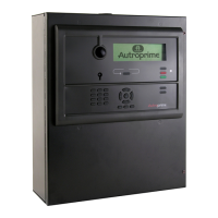
9.4.2 Connections to Connector J2, Power Board BSF-400
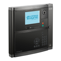
9.4.3 Example of the Interconnection of Several Power Cabinets
The example below shows the interconnection of two Power Cabinets
on the AutroFieldBus. Note that the AutroFieldBus always goes from
AFB A on the main terminal block inside BS-420/BC-420 to AFB B on
the J2 connector on the Power Board BSF-400, then from AFB A to
the next unit. The cable finally returns to AFB B on the main terminal
block.
A
B
Fire Alarm Control
Panel BS
-420 /
Controller BC-420
/
BC-
440
B
A
B
A
Power Cabinet
BP-
405
(Power Board
BSF-400)
L
1.9
L
1.
11
L1.3 L1.5
J2
.5
J2.
6
J2.
1
J
2.2
J2.
5
J
2.6
J2.1
J
2.2
1
2
3
AFB A
AFB A"
AFB CT A
4
5
6
AFB Earth Fault Sense
AFB B
AFB B"
7
8
AFB CT B
AFB Earth Fault Sense
J2
J26
1 6
1
2
3
Alarm NO
Alarm Com
RC (Remote test)
4
5
6
Fault Relay NO
Fault Relay NC
Fault Relay Com
F1 A1 F2AL
F2 A2 F2AL
J19
S1 Reset
8 Internal Fault
0V
+
A1
S5
AFB Earth Fault Off
AFB Earth Fault On
1
OFF
ON
2
OFF
ON
J2

Table of Contents

Other manuals for Autronica Autro Safe

Questions and Answers:

Question and Answer IconNeed help?

Do you have a question about the Autronica Autro Safe and is the answer not in the manual?

Autronica Autro Safe Specifications

General IconGeneral
BrandAutronica
ModelAutro Safe
CategorySmoke Alarm
LanguageEnglish