EasyManuals Logo

Autronica Autro Safe User Manual

Autronica Autro Safe
88 pages
To Next Page IconTo Next Page
To Previous Page IconTo Previous Page
Page #64 background imageLoading...
Page #64 background image
Appendix A - Controller Board BSA_400
Installation Handbook, AutroSafe Interactive Fire Detection System, Release 4, 116-P-ASAFE-INSTALL/DGB Rev. I, 2014-04-01,
Autronica Fire and Security AS
Page 64
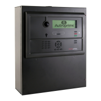
14.4 Internal LED Indicators
LED
Colour
Function
D1
Yellow
SD-Card activity indicator
D2
Yellow
USB Boot Time Rescue upgrade in progress
D3
Yellow
System fault LED, ON when system is locked in system fault
D13
Green
AutroFieldBus TX
D15
Green
NA
D16
Green
Power indicator
D17
Red
AutroFieldBus RX
D18
Red
NA
D19
Red
Serial Port activity indicator
D20
Red
System reset 5V
D21
Red
System reset 3,3V
D22
Blue
System heart beat
D23
Blue
NA
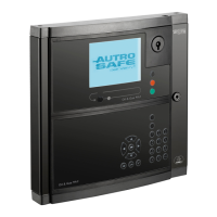
14.5 Power Input Connector J18 (screw terminal)
Connector J18 on
Controller Board BSA-400
Description
Connection to Power Board BSF-
400
J18.1
+24V DC In 1
Interconnection
A1 +
J18.2
0V In 1
A1 0V
J18.3
+24V DC In 2
A2 +
J18.4
0V In 2
A2 0V
D20 D21
D13 D17
D23 D2
D22 D1
D19 D16
D18 D15
D3
J18
BSA-400
BSA-400

Table of Contents

Other manuals for Autronica Autro Safe

Questions and Answers:

Question and Answer IconNeed help?

Do you have a question about the Autronica Autro Safe and is the answer not in the manual?

Autronica Autro Safe Specifications

General IconGeneral
BrandAutronica
ModelAutro Safe
CategorySmoke Alarm
LanguageEnglish