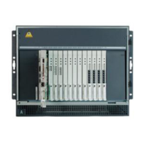
Configuring the SNMP subagent in the Avaya Ethernet switch (if used)
Issue 4.1 June 2005 35
To administer the Ethernet switch(es):
1. Plug the Ethernet switch power cord into the back of the switch and the back of a UPS.
● For a single control network—connect Ethernet switch 1 for Control Network A (CNA)
into UPS 1.
● For a duplicated control network—connect Ethernet switch 1 for CNA into UPS 1 and
connect Ethernet switch 2 for Control Network B (CNB) into UPS 2.
2. Connect the services laptop computer (RS-232 serial port) to the port labeled Console on
the front of Ethernet switch 1 (CNA) using the flat cable supplied with the Avaya Ethernet
switch.
3. On the services laptop open a VT-100 terminal emulation session.
4. Administer the terminal emulation port settings:
● 9600 baud
● No parity
● 8 data bits
● 1 stop bit
5. Follow the instructions in the Quick Start Guide.
6. Set the following parameters:
● IP address and subnet mask of the Ethernet switch(es)
- For Ethernet switch for CNA, the defaults are 198.152.254.240, 255.255.0.0.
- For Ethernet switch for CNB, the defaults are 198.152.255.240, 255.255.0.0.
● IP address of the trap receiver. (Do not use the Active Server IP address.)
- For Ethernet switch for CNA, this is the IP address of media server 1. (default is
198.152.254.200)
- For Ethernet switch for CNB, this is the IP address of media server 2. (default is
198.152.255.200)
● SNMP community string for Get, Set, and Trap. (See the section on SNMP commands
on the documentation CD that comes with the Avaya Ethernet switch.)

 Loading...