EasyManuals Logo

Avaya S8100 Series Installing And Configuring

Avaya S8100 Series
112 pages
To Next Page IconTo Next Page
To Previous Page IconTo Previous Page
Page #92 background imageLoading...
Page #92 background image
Testing the media server installation
92 Installing and Configuring the Avaya S8700 Series Media Server
Figure 14: TN2312BP circuit pack faceplate
Figure notes:
1. Red
LED
2. Green LED
3. Amber LED
4. Yellow LED (Tone Clock status)
5. Emergency Transfer LED
6. Services RJ45 connector
7. Network Control RJ45 connector
8. 4-character LED display
9. Pushbutton switch
10. Slot for maintenance cable
ckdfips2 KLC 091403
CLK
S
E
R
V
I
C
E
N
E
T
W
O
R
K
700060643
AVAYA
01DR06142246
TN2312AP IPSI
3
4
5
8
9
1
2
6
7
10
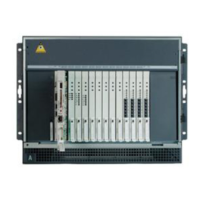
Table of Contents

Other manuals for Avaya S8100 Series

Questions and Answers:

Question and Answer IconNeed help?

Do you have a question about the Avaya S8100 Series and is the answer not in the manual?

Avaya S8100 Series Specifications

General IconGeneral
BrandAvaya
ModelS8100 Series
CategoryServer
LanguageEnglish

Related product manuals