Install the Core Series boards in E1 enclosure
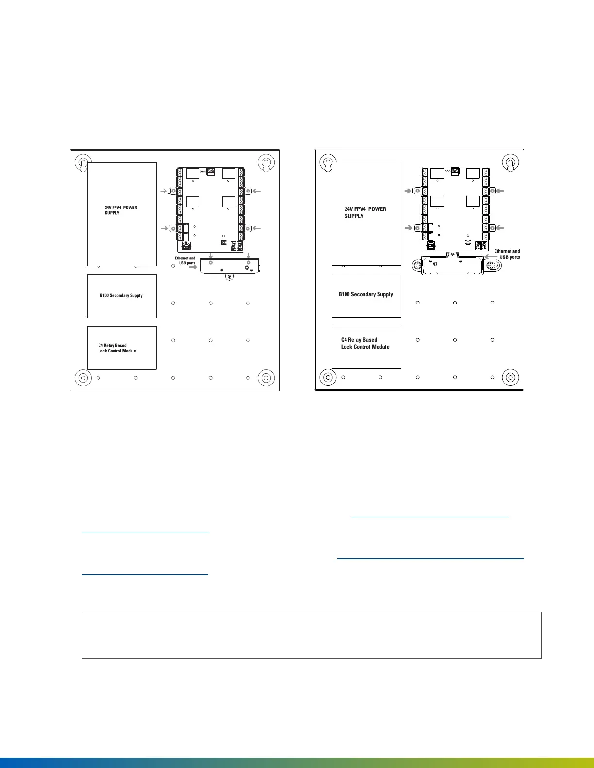
The E1 board placement includes the 24V FPV4 supply, B100 secondary supply, C4 Relay Based Lock Control
Module, 4-Port Board, and Access Control Core with or without the mounting bracket.
Front view
Figure 1 Access Control Core mounted without bracket (Ethernet and USB
ports facing left) below 4-Port Board
Figure 2 Access Control Core mounted with bracket (Ethernet and USB
ports facing right) below 4-Port Board
Mounting
1. Mount the 4-Port Board to the right of the LifeSafety Power supply modules by snapping the board
standoffs into the enclosure (see arrows).
2. If mounting the Access Control Core without the bracket, see Install Access Control Core without
mounting bracket on page13. Ensure the Ethernet and USBports face left.
If mounting the Access Control Core with the bracket, see Install Access Control Core with mounting
bracket on the previous page. Ensure the Ethernet and USB ports face right.
3. Connect the Access Control Core to the 4-Port Board with the included USB cable.
Note: The maximum recommended USB cable lengthis 6 feet (2 meters) or 10 feet (3 meters) if high
quality, shielded cable.
Installation 15
 Loading...