Wiring the Core Series 24V Elevator Smart Hub
The Core Series 24V Elevator Smart Hub (SYS-ELEV-SVE1)uses the LifeSafety Power FPV4to power the Access
Control Core, and 16 I/O Elevator Board.
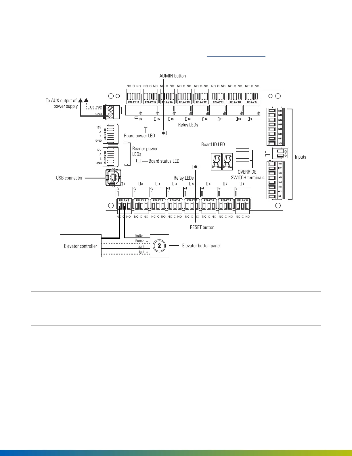
Figure 16 SYS-ELEV-SVE1 wiring diagram
USB connector Connects to the Access Control Core board.
Relays 1–16 Output ratings: 16 relays, 60VDC maximum; 1A @ 24VDC (resistive); 0.5A @ 125VAC
(resistive). The pin order is the same on both sides of the board, left to right (for
example, NC, C, NO), which allows connectors to be moved without rewiring.
Inputs 1–16 General-purpose inputs require a voltage between 3V and 24V.
1. For 12V or 24V systems, connect the 16 I/O Elevator Board to an unswitched output from the main power
supply (AUX output on the FPV4).
2. Use the provided USB cable to connect the 16 I/O Elevator Board to the USB connector on the Access
Control Core board.
Installation 46
 Loading...