Standard wiring configurations
Wiring the Core Series 12/24V 4-Door Smart Hub
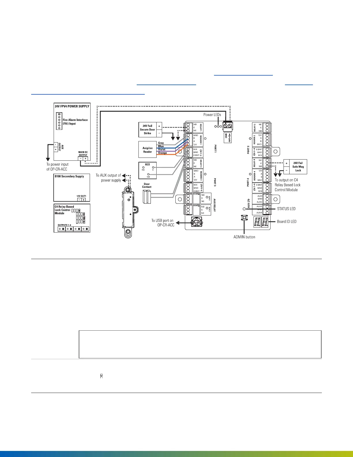
The Core Series 12/24V 4-Door Smart Hub (SYS-4ENT-DVE1)uses the LifeSafety Power FPV4to power the
Access Control Core and 4-Port Board; a LifeSafety Power B100secondary power supply; and the LifeSafety
Power C4 Relay Based Lock Control Moduleto power 12-24V locking hardware.
Figure 15 SYS-4ENT-DVE1 wiring diagram
24V FPV4
Power Supply
The main output can be switched by the Fire Alarm Interface (FAI).
Fail safe and fail secure are ways of configuring lock hardware:
l
Fail-safehardware
unlocks
when power is interrupted or lost.
l
Fail-securehardware
locks
when power is interrupted or lost.
For information about wiring third-party lock hardware, refer to vendor documentation.
Note: Ensure that locking hardware is connected to the required voltage by setting the
jumpers on the C4 Power Control Module.
*OUTPUTS1–
4
The voltage of each C4 output can be selected individually as 12V or 24V using the yellow
jumper corresponding to the output: position 1 on the jumper pins is 24V (this is the
default setting) and position 2 is 12V.
Installation 45
 Loading...