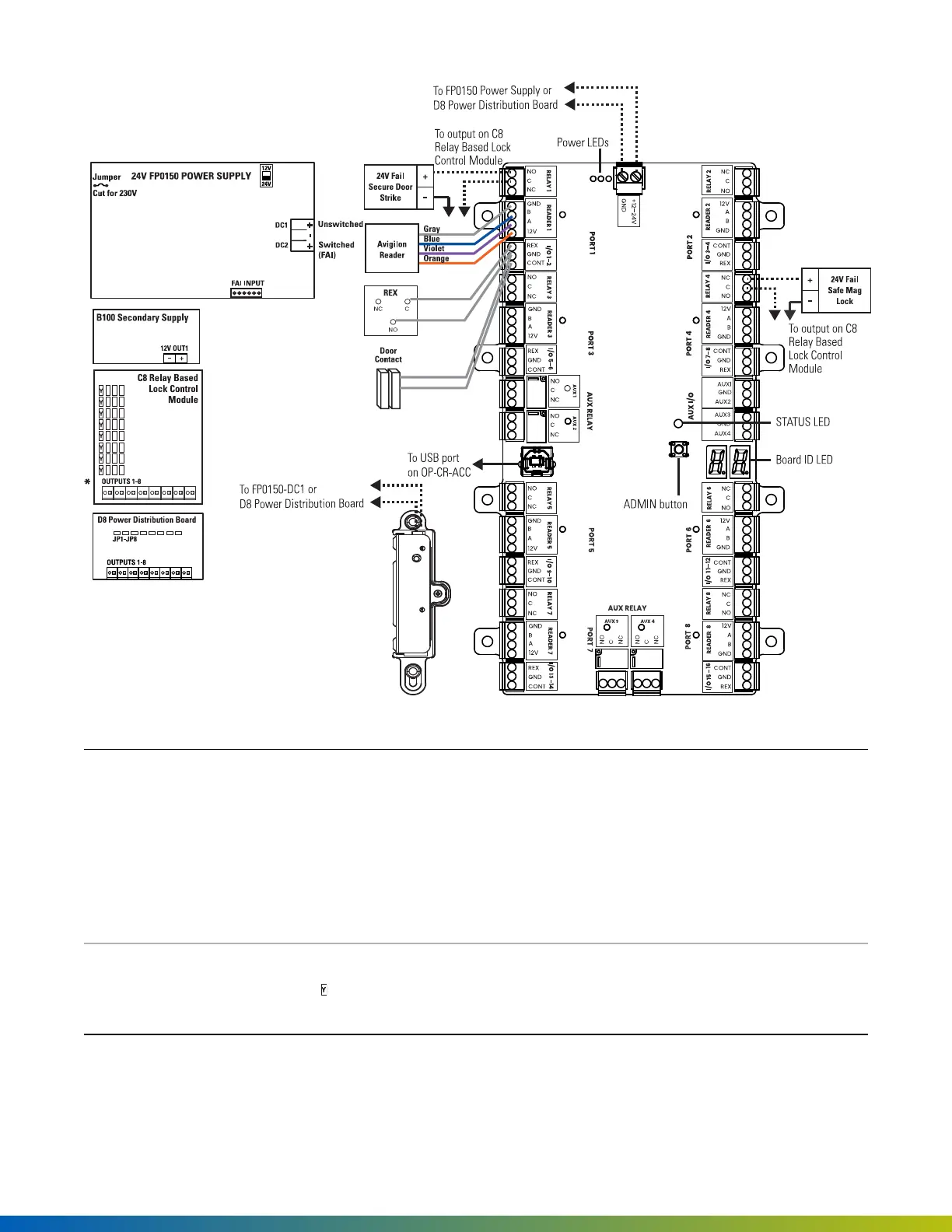
Figure 18 SYS-8ENT-DVE4wiring diagram
24V FP0150
Power Supply
The main output can be switched by the Fire Alarm Interface (FAI).
Fail safe and fail secure are ways of configuring lock hardware:
l
Fail-safehardware
unlocks
when power is interrupted or lost.
l
Fail-securehardware
locks
when power is interrupted or lost.
For information about wiring third-party lock hardware, refer to vendor documentation.
*OUTPUTS 1–
8
The voltage of each C8 or D8 output can be selected individually as 12V or 24V using the
yellow jumper corresponding to the output: position 1 on the jumper pins is 24V (this is
the default setting) and position 2 is 12V.
Installation 49
 Loading...