Installation
24
F-FEM-CON — User’s Guide
3.2.3
Connections
1. To work with the device, connections at the following connectors must be
established:
– IEEE1394 (at least 1 cable at X21, X22 or X23)
The wiring must be tree-like to avoid loops. All 3 sockets are equiva-
lent. There is no priorization. The signal transmission times are inde-
pendent of the topology of the wiring.
– 24 V supply at X11
– At least 1 cable at X1 ... X8, X15 ... X18, X29 or X30
– Add-On (at X24 or X25, if required)
2. The pin assignment needs to be checked (please refer to Location of Plug
Connections on page 84). For details, please refer to the test bed circuit dia-
gram.
3.2.4
Function Test
If the power supply has been switched on and the pin assignment is correct, a
figure or 2 strokes appear on the seven-segment display on the front side of the
F-FEM-CON.
• If this is not the case, check all steps of the installation.
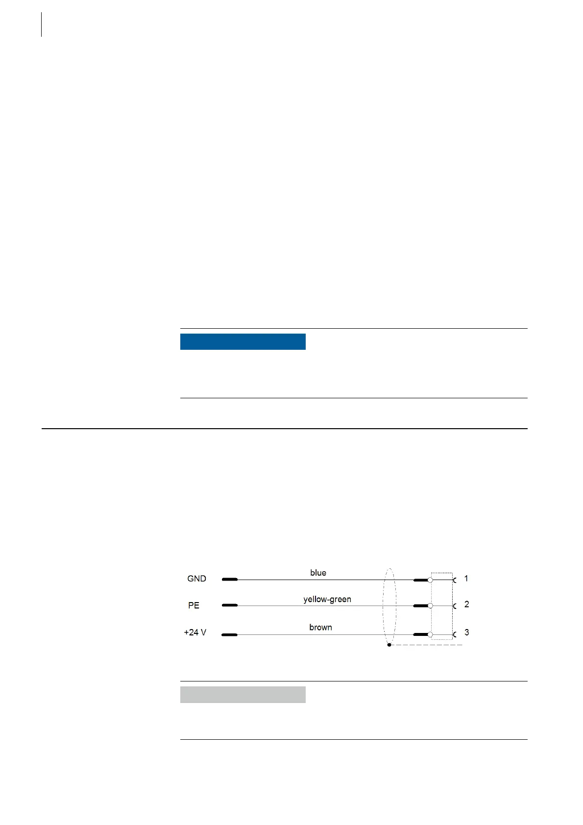
3.3 Electrical Installation
Each F-FEM has to be supplied with 24 V via X11.
For the data transfer to the automatization system (test bed workstation) an
IEEE1394-connection is to be set up.
Several F-FEMs are connected by connecting their IEEE1394 interfaces (X21,
X22, X23).
3.3.1
Power Cable Inlet
NOTICE
Do not open the closed module case! There are no parts in the interior of the
device that need to be exchanged. Warranty claims can no longer be asserted if
the housing is opened.
Fig. 7
Information
Pull shield back over isolation and fix it with the screws of the strain to the
connector case on both sides!
 Loading...

