Operation
72
F-FEM-CON — User’s Guide
4.7.2.3
Signal type: Signal Splitter (SiSp)
In connection with the two counter inputs, the two frequency outputs can be used
as signal splitter (SiSp). All possible counter input settings can be used as a
source. Various conversion methods can be combined with the frequency
outputs using the firmware. These conversion methods are described below.
SiSp Counter 1 DABZ and/or SiSp Counter 2 DABZ
In the "Direct ABZ" mode, all 3 tracks of counter 1 are output at F-OUT 1
unchanged (= directly) and all 3 tracks of counter 2 are output at F-OUT 2.
This is the method with the least delay because the looping-through of the
counter signals is realized exclusively by the hardware. Crossbonding of
tracks 1 and 2 as well as doubling are possible (e.g. counter channel 1 is
output at FOUT 1 and FOUT 2).
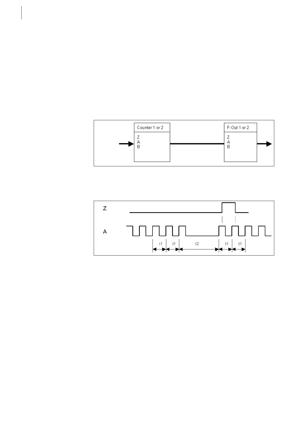
Block diagram SiSp Counter n DABZ:
If a toothed disk with 60-2 teeth is used as speed encoder (1 or 2 tracks), a pulse
is generated at the zero track of the frequency output (top dead center) after the
absence of the two teeth has been detected.
SiSp Counter 1 DZ and/or SiSp Counter 2 DZ
In the „Direct Z" mode, the frequencies are measured at the counter chan-
nels 1 and 2 and are output again at F-OUT 1 and F-OUT 2 after having
been multiplied (divided) by a factor (marks).
The measured zero track frequency is output unchanged. The position of
the original dead center is retained. Crossbonding of the channels 1 and 2
is not possible.
The relation to the zero track (TDC relation) is maintained (the counter zero
track and the F-OUT zero track are phase locked). As a result of the conver-
sion of tracks A and B, the phase relation between A, B and Z at the output
is lost, although A and B remain in quadrature.
Fig. 48
Fig. 49
 Loading...

