Operation
70
F-FEM-CON — User’s Guide
4.7.2
Description of Modes
The two frequency outputs can be used in different ways. All possible signal
types are explained below. Only the description for channel 1 is given; it is iden-
tical for channel 2.
4.7.2.1
Signal type: PWM, PWM inverted
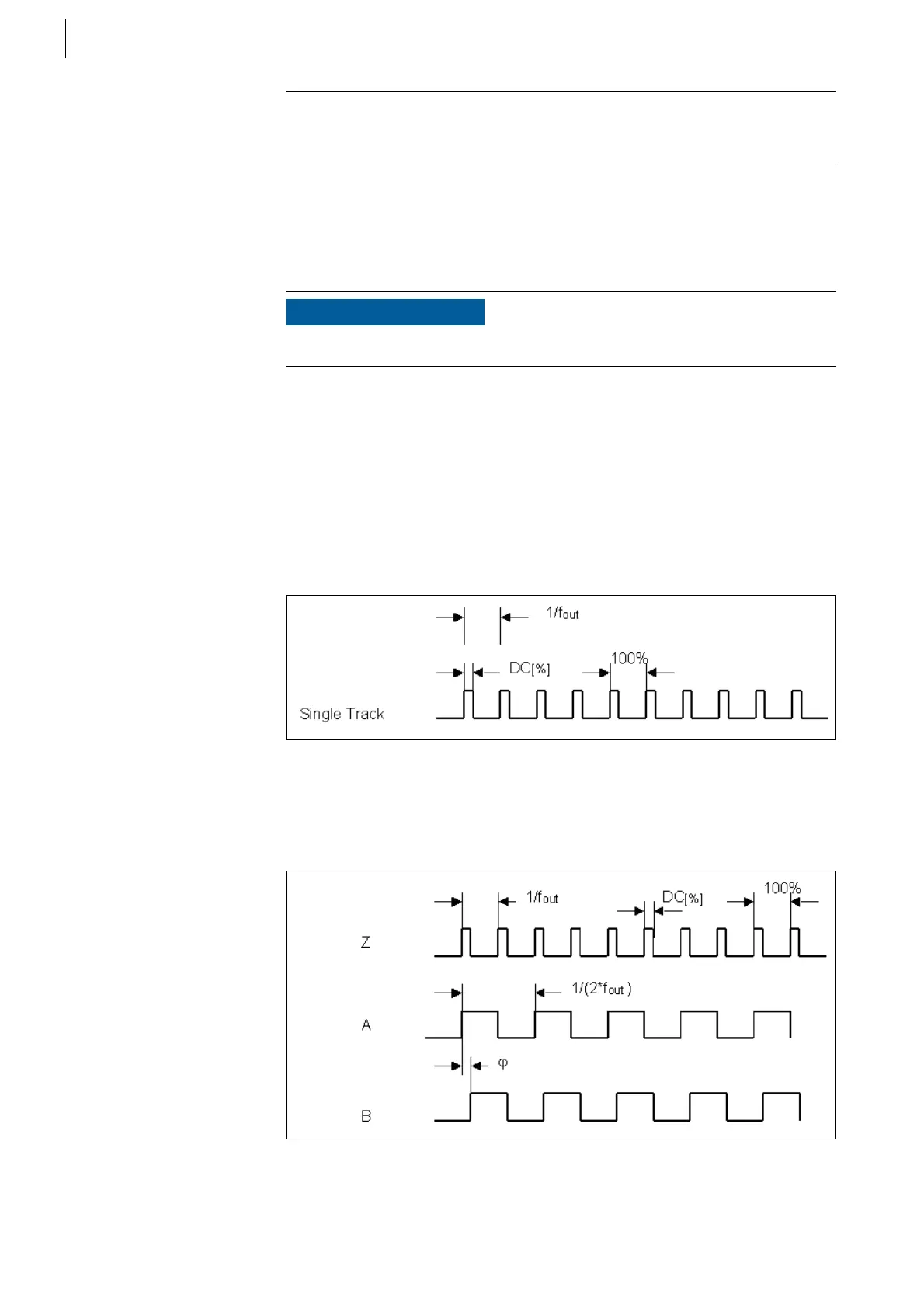
The desired frequency (single-track signal) is output at the single channel with
the desired duty cycle.
F-Out PWM single channel:
The desired frequency is output by halves at tracks A and B, whereby the phase
shift of both tracks corresponds to the desired duty cycle (0 - 100% corresponds
to 0 - 180°)
F-Out PWM tracks Z, A, B:
Example
The desired output quantity (demand torque of 20 – 200 Nm) is mapped to a
frequency range of 200 Hz to 2000 Hz. The duty cycle is always 50 %.
NOTICE
Some of the functionalities described require the firmware revision 3.0.x.
Fig. 43
Fig. 44
=
=
·
 Loading...

