77
Operation
F-FEM-CON — User’s Guide
4.7.4.2
Electrical Values
Relationship between duty cycle and phase angle:
respectively:
4.7.5
Realization of an Analog Output by F-Out (PWM)
A pulse-width modulated (PWM) digital signal can be reconverted into ananalog
signal using an integrator (e.g. a simple RC filter). We choose 10 kHz as the
basic frequency. A voltage between 0-10 V should be generated by varying the
duty cycle between 0 - 100 %. The single-channel output at the frequency output
(pins 8 and 9) has a voltage amplitude of approx. 5 V. Should a higher voltage
amplitude (e.g. 10 V) be required, this can be achieved by means of an auxiliary
voltage at pin 7 (approx. 12 to 24 V).
The RC-filter must be dimensioned in accordance with the input resistance of the
consumer load and the requested ripple. For our purposes, it is sufficient to
assume that the integration time constant is at least 100 times higher than the
carrier frequency. Thus, a resistance of 100 Ohm and a capacity of approx.
47 µF is recommended.
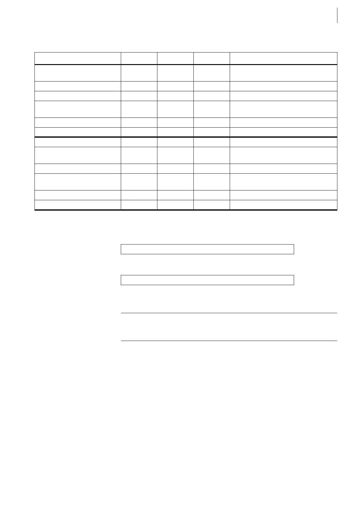
Quantity Min. Max. Unit Remark
Outputs
at Pins 1 ... 6
Differential outputs according to EIA
standard RS422
Output voltage High 2.5 V With load of 100 Ω
Output voltage Low 0.5 V With load of 100 Ω
External voltage applied
to the outputs
30 V Referred to Pin 9
without damage
Output Current 30 mA Short circuit-proof
Rise/fall time 6 ns Load: 40 pF parallel 100 Ω
Output at Pin 8 Single channel, single track
Output voltage High 4.5 15 V Maximum value
when applying 24 V at Pin 7
Output voltage Low 0.5 V
External voltage applied
to the output
30 V Referred to Pin 9
without damage
Output Current 50 mA Short circuit-proof
Rise/fall time 40 ns Load: 2.2 nF
Tab. 16
Duty Cycle [%] = Phase Angle [°] / 3.6
Phase Angle [°] = Duty Cycle [%] * 3.6
Example
The speed demand value (0 - 10000 rpm) is to be realized as a voltage output
(frequency output) in a closed control loop. The output voltage is 0 ... 10 V.
 Loading...

