Operation
52
F-FEM-CON — User’s Guide
4.5 Digital Outputs
4.5.1
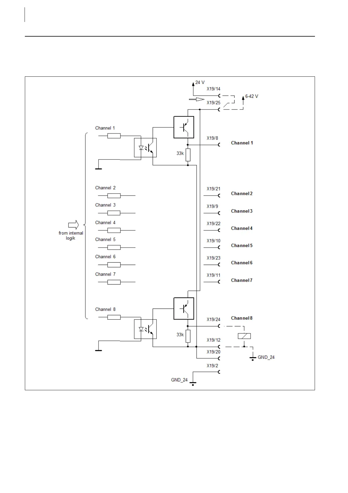
Block Diagram
This basic wiring applies to the connectors X12, X19 and X20. The outputs at
X14 are connected to the internal 24V power supply.
The switching transistors delimit the inductive load dump voltage to approx. 56 V.
If this voltage is too high for certain loads, a freewheeling diode must be used to
reduce the inductive load dump voltage.
A group of 8 outputs has a common power supply (typically 24 V) and a common
GND.
Fig. 28
 Loading...

