Operation
36
F-FEM-CON — User’s Guide
4.1.1
Block Diagrams
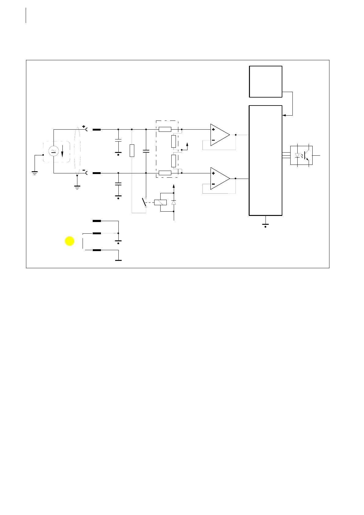
Analog input for voltage measurement range
The pin assignment above applies to X1, X2, X3 and X4.
Fig. 18
A IN-
Provide shielding
at connector
housing
X1/2
X1/1
500
Ω
Current
2,5 V
93k
Ω
93k
Ω
410k
Ω
410k
Ω
ADC
X1/4
X1/5
X1/9
5 V
A IN+
V ref = 2,5 V
Reference
u
*1
1..... The electrical isolation between the analog and the digital ground may be removed by bridging X1/5 and
X1/9, if necessary. In this case, the specification as given in the column "Without Isolation" applies, please
see chapter Specifications on page 42.
 Loading...

