Operation
50
F-FEM-CON — User’s Guide
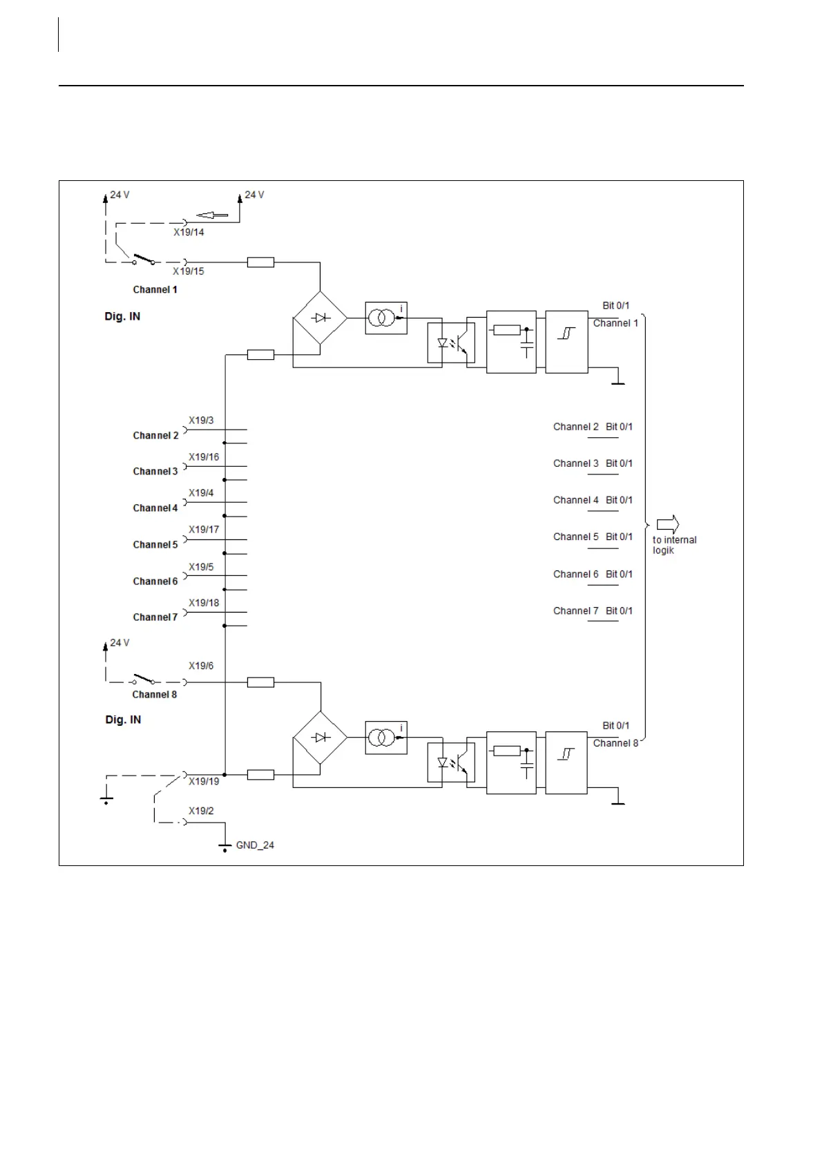
4.4 Digital Inputs
4.4.1
Block Diagram
The pin assignment above applies to X19 and X20.
The digital inputs are reverse battery protected and bipolar, i.e. there is no
explicit + and - contact. If the digital inputs are used to monitor a consumer with
high inductance (e.g.: Digital output powers a relay and is fed back to a digital
input), the load dump voltage must be limited to the switching threshold for logic
low.
A group of 8 inputs has a common reference potential (Common). This common
reference potential can be connected to +24 V (Common source) or to ground
(sink circuit), as shown in the figure above.
Fig. 27
 Loading...

