Operation
92
F-FEM-CON — User’s Guide
4.12.8
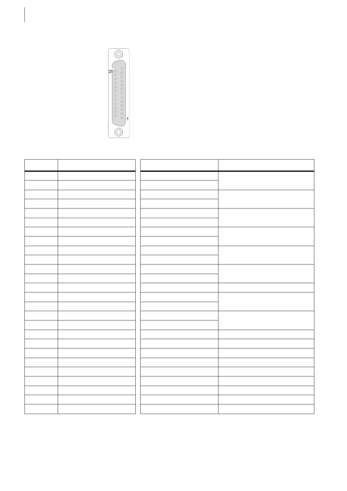
Counter Inputs X17, X18
If two sensors are connected at X17 or X18, two cables lead into the connector
housing.
Fig. 65
Pin Signal at X17 Signal at X18 Comment
5 IND1+ IND2+ Inductive pick-up
17 IND1– IND2–
7 + 5 V + 5 V Incremental encoder supply
20 + 5 V + 5 V
6 U1_0+ U2_0+ Zero track
18 U1_0– U2_0–
8 U1_1+ U2_1+ Track A
21 U1_1– U2_1–
9 U1_2+ U2_2+ Track B
22 U1_2– U2_2–
10 DGND DGND Incremental encoder supply
23 DGND DGND
13 + 24 V + 24 V (OUT for DI)
11 DI1 A DI2 A Track A
24 DI1 A DI2 A
12 DI1 B DI2 B Track B
25 DI1 B DI2 B
16 GND_24 GND_24
14 Hall1 A Hall2 A Track A
15 Hall1 B Hall2 B Track B
2 GND_17 GND_18 for Hall
3nc nc
4nc nc
1 Shielding Shielding
19 Shielding Shielding
Case Shielding Shielding
Tab. 28
 Loading...

